Pipeline Integrity
Comprehensive Pipeline Integrity Inspections and Solutions
Pipeline integrity is critical to ensure your systems operate safely, efficiently, and meet regulatory compliance. At XCEL, we provide accurate and reliable pipeline integrity inspections and direct assessments, helping you maintain operational excellence and extend the lifecycle of your assets.
We specialize in both conventional NDT services and advanced NDT services, offering tailored solutions that leverage cutting-edge technologies like automated ultrasonic testing (AUT) and phased array ultrasonic testing (PAUT).
- UT SHEARWAVE
- LASER MAPPING
- POSITIVE MATERIAL IDENTIFICATION
- UT THICKNESS
- AUT CORROSION MAPPING
- VISUAL
- MAGNETIC PARTICLE
- PIPE TO SOIL POTENTIAL
- SOIL RESISTIVITY
- COATING INSPECTION
- TIME OF FLIGHT DIFFRACTION
- SOIL pH
- PHASED ARRAY ULTRASONIC
- ENTRAPPED WATER pH
PIPELINE INTEGRITY
Ultrasonic Shearwave Testing (UTSW)
Ultrasonic shearwave testing (UTSW) is a critical tool in pipeline integrity direct assessments, providing reliable and accurate data to ensure the safety and longevity of pipeline systems. Its non-destructive nature and ability to detect various types of flaws make it an essential technique for the maintenance and monitoring of pipelines. Conducted by experienced NDT Level III personnel and in compliance with ASME Code requirements, UTSW ensures high-quality results for piping and vessel fabrication facilities.
This technique uses high-frequency sound waves to detect, measure, and characterize sub-surface and surface-breaking flaws.
Applications for Ultrasonic Shearwave Testing (UTSW):
- Weld evaluation
- Detecting/characterizing internal corrosion, pitting, or other internal mill-related defects such as inclusions and lack of weld fusion
- Long seam evaluation
- Stress Corrosion Cracking (SCC) evaluation
PIPELINE INTEGRITY
LASER MAPPING
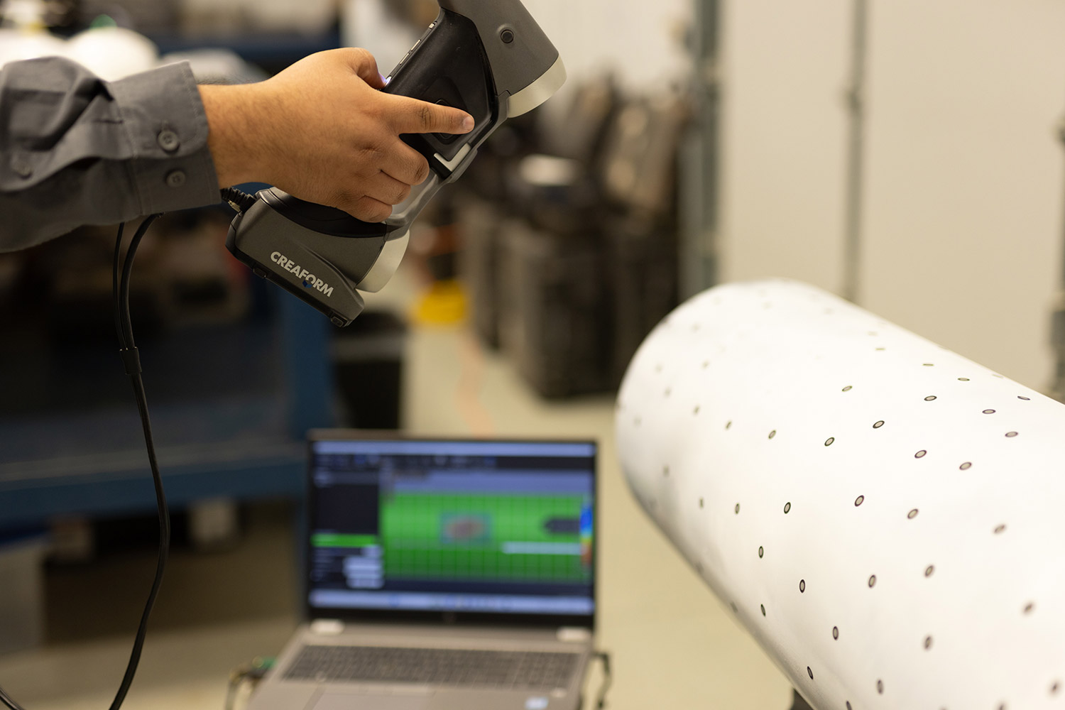
Laser profilometry, often referred to as laser mapping, provides surface detail and measurements with unmatched accuracy and coverage levels, far beyond what is achievable through traditional mechanical methods. This non-contact, nondestructive technology is ideal for capturing precise measurements on contoured surfaces, such as fittings and saddles, where physical measurements are challenging or impractical. Using lasers and reflector dots for orientation, laser mapping digitally captures an object’s exact surface characteristics and converts it into a 3D digital representation.
Creaform Portable 3D Laser Mapping Scanner
The Creaform handy scanner offers the fastest solution on the market for data acquisition and with help from the Pipecheck offered with the scanning system, we can also boast the fastest analysis and report turn arounds. The Creaform scanner covers the accuracy, simplicity, portability and traceability that clients demand in a competitive market.
Pipecheck has corrosion software that utilizes ASME B31, B31G, B31G Modified, and Effective Area Method to evaluate a pipeline’s fitness for service in a fast and reliable way. Here are the key features offered with the Corrosion software.
Pipecheck Corrosion Software
Utilizing ASME B31, B31G, B31G Modified, and the Effective Area Method, Pipecheck evaluates pipeline fitness for service quickly and reliably.
Key Features:
- Interaction rules automatically applied
- Burst pressure calculations (ASME B31G, B31G Modified, Effective Area methods)
- Worst-case-profile and customizable grid resolution
- Feature dimensions (length, width, maximum depth) extracted for all features
- Snipping tool for additional reporting
- Internal and external surface assessments or true wall thickness evaluations
- 3D and 2D colormap with river-bottom path overlay
- Quick, on-the-fly depth analysis with hover functionality
Pipecheck Mechanical Damage Software
This software analyzes mechanical damage, such as dents, gouges, and localized surface deformations.
Key Features – Depth-Based Assessment:
- Automatic maximum depth measurement using straight-edge techniques
- 3D and 2D depth colormaps
- Automatic 3D cross-section creation
- Depths over diameter ratio
- Snipping tool for reporting
- Depths extracted using Creaform’s virtual pit gauge tool
- Maximum diameter found at 90 degrees of the dent
Key Features – Strain-Based Assessment:
- Automatic maximum strain detection
- 3D and 2D strain colormaps (all strain components)
- Results for decomposed values: circumferential bending, longitudinal bending, longitudinal extensional, effective strain on inside and outside surfaces, and maximum effective strain value
With its advanced capabilities, Laser Mapping and the Creaform system ensure compliance with ASME Code requirements while delivering reliable, high-quality results for NDT and Inspection services in a competitive market.
Pipecheck Mechanical damage software analyzes mechanical damage, such as dents, gouges and other localized surface deformations. Here are the key features offered with the mechanical damage software.
Key Features
Depth-Based Assessment Type
- Automatic maximum depth measurement using straight edge technique in both directions
- 3D and 2D depth colormaps
- Automatic 3D cross-section creation
- Depths over diameter ratio
- Snipping tool for additional reporting information
- Depths extracted from Creaform’s virtual pit gauge tool
- Maximum diameter found at 90 degrees of the dent
Key Features
Strain-Based Assessment Type
- Automatic maximum strain detection
- 3D and 2D strain colormap (all strain components)
- Results for decomposed values: circumferential bending, longitudinal bending, longitudinal extensional, effective strain on inside and outside surface of the pipe as well as maximum effective strain value.
PIPELINE INTEGRITY
Positive Material Identification (PMI)
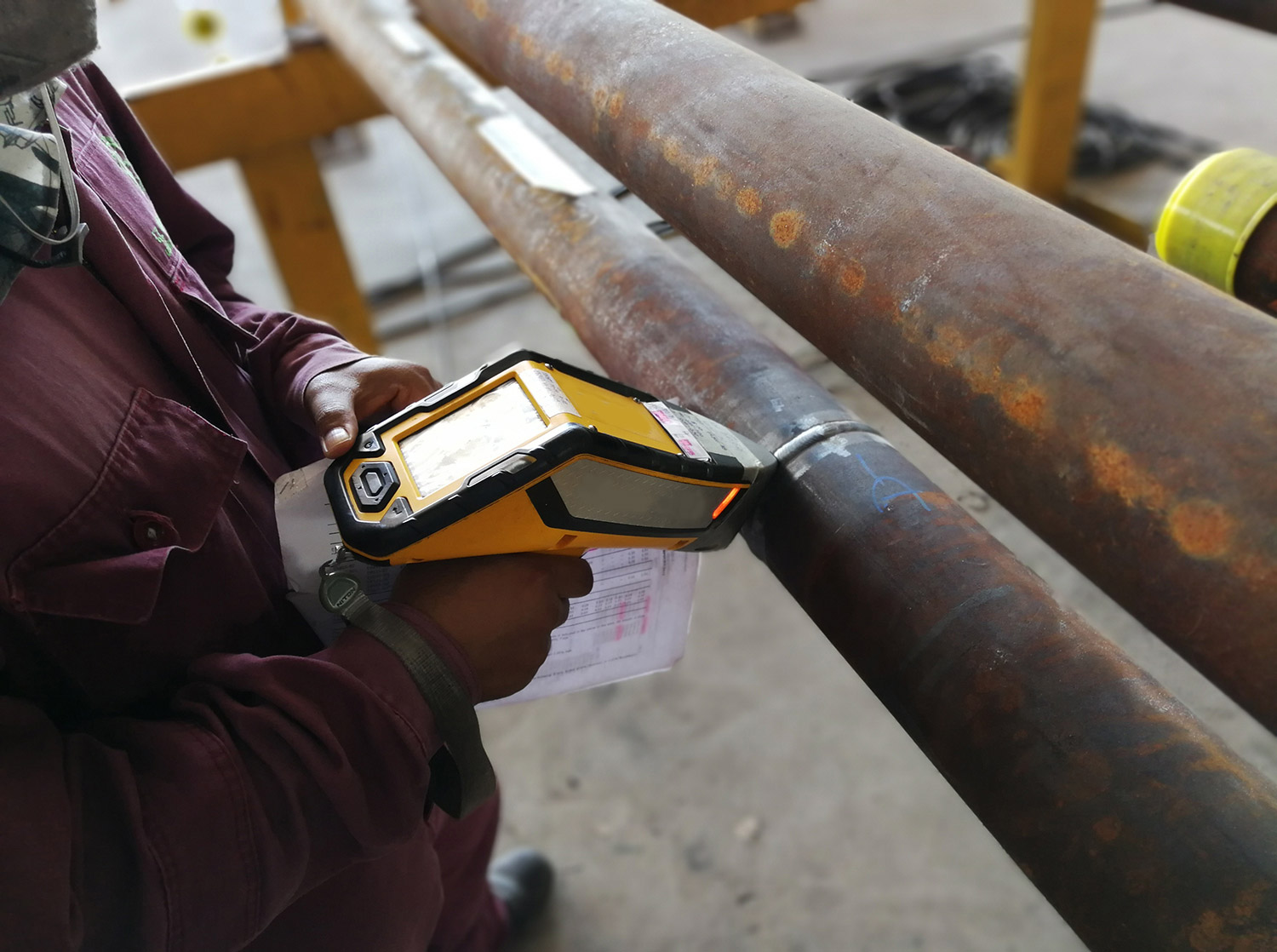
Positive Material Identification (PMI) is extensively used to sort and identify materials and fittings, ensuring their fitness for purpose. This method analyzes the chemical composition of metals and alloys, playing a vital role in production and asset integrity management programs across industries such as oil and gas, power, petrochemical, nuclear, and fabrication.
PMI verifies that a fitting, pipe, or other material possesses the required elements for its specific material specification. Installing incorrect materials can lead to premature or catastrophic failures, making PMI an essential part of NDT and inspection services.
Techniques for Positive Material Identification:
- Optical Emission Spectroscopy (OES): Analyzes chemical elements, including carbon and lighter elements. Newer portable OES systems offer improved durability and portability, similar to handheld XRF systems.
- X-Ray Fluorescence (XRF) Analyzer: The most common method, using portable handheld equipment for on-site analysis. While effective, it cannot detect carbon or lighter elements.
- Laser Induced Breakdown Spectroscopy (LIBS): A portable “OES” instrument commonly used for Carbon Equivalency (CE). It features an integrated argon cartridge for enhanced portability.
Applications of Positive Material Identification:
- Verifying the chemical composition of metals and alloys
- Detecting misidentified alloys
- Ensuring materials meet ASME Code requirements and customer specifications
- Confirming welded components were made with the correct filler material
Advantages of PMI:
- Quick and accurate analysis
- Highly portable, handheld digital technology
Limitations of PMI:
- X-ray penetration depth is less than 0.001”, requiring technicians to ensure the examined area represents the entire piece
- Surface accessibility and preparation may be needed
- Analyzers are limited to identifying alloys listed in the manufacturer’s library
- Carbon, sulfur, and phosphorus cannot be identified using the XRF method
- Instruments must maintain surface contact with the material
With its advanced capabilities, PMI ensures compliance with ASME Code standards and supports the needs of piping and vessel fabrication facilities, delivering reliable results for NDT and inspection services.
PIPELINE INTEGRITY
UT Thickness
Ultrasonic Thickness Testing utilizes Ultrasonic Straight Beam and other ultrasonic NDT flaw detection techniques that employ sound energy during the testing process. This method is essential for NDT and Inspection services, providing accurate and reliable data for assessing material integrity.
Straight Beam Testing operates on the principle that sound energy propagates through a medium until it either disperses or reflects off a boundary, such as air surrounding a far wall or a gap caused by a flaw. During testing, the operator pairs the transducer with the test piece and identifies the echo returning from the far wall (the ‘backwall signal’). Any additional echoes ahead of the backwall signal or shifts in the signal may indicate the presence of laminar cracks, voids, or other discontinuities. Further analysis determines the depth, size, and shape of the structure causing the reflection.
With its advanced capabilities, Ultrasonic Thickness Testing ensures compliance with ASME Code requirements and supports the needs of piping and vessel fabrication facilities, delivering reliable results for NDT and Inspection services.
Normal/Angle Beam
Normal beam testing introduces a sound beam at 90 degrees to the surface, ideal for thickness testing, while angle beam testing introduces the beam at an angle other than 90 degrees. The choice depends on the orientation of the discontinuities, as the sound beam should be as perpendicular as possible to the discontinuity’s primary axis for maximum reflection.
Applications for Ultrasonic Straight Beam Testing
- Flaw detection, including parallel cracks, inclusions, porosity, and laminations
- Erosion/corrosion thickness gauging and mapping
- Assessment of bond integrity
Advantages of Ultrasonic Straight Beam Testing
- • Detects surface and subsurface discontinuities
• Superior depth penetration compared to other test methods
• Requires only one-sided access with the pulse-echo technique
• Accurately estimates discontinuity size and shape
• Minimal surface preparation needed
• Immediate results with electronic equipment
• Can be automated, producing detailed images
Limitations of Ultrasonic Straight Beam Testing
- Surface must be accessible
- Requires a couplant to promote sound transfer
- Surface roughness, certain castings, or exceptionally thin materials can be challenging to inspect
- Linear defects oriented parallel to the sound beam may go undetected
PIPELINE INTEGRITY
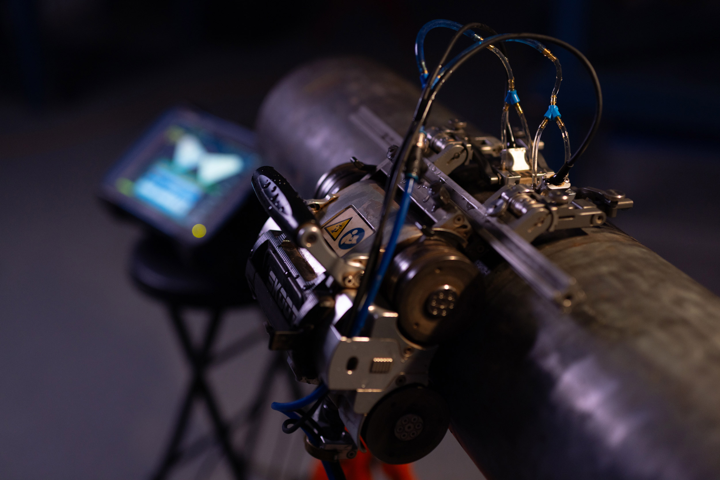
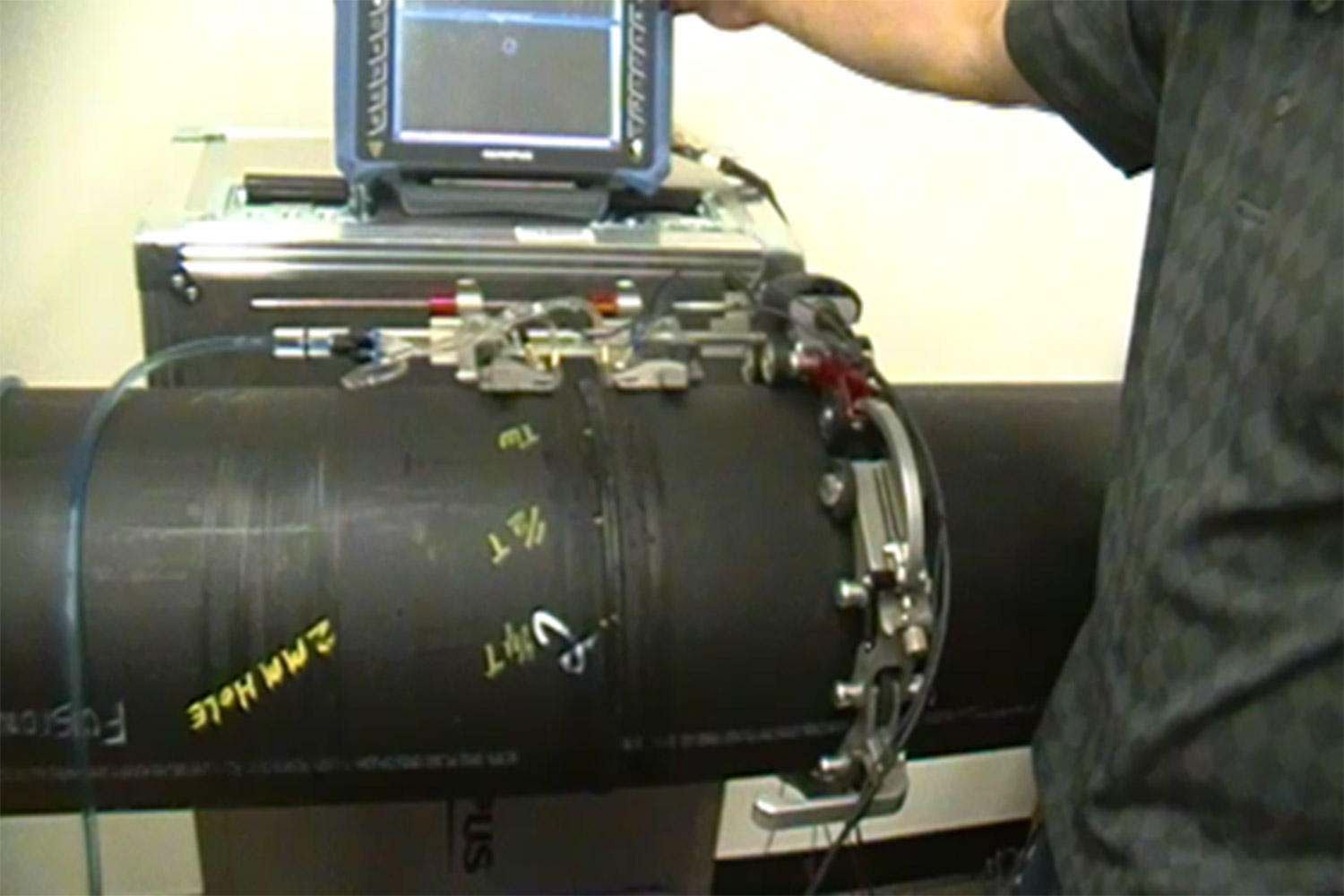
AUT Corrosion Mapping
AUT corrosion mapping delivers detailed insights into wall loss, topography, and remaining thickness of pipeline materials. Using advanced NDT solutions, this technology provides a high degree of repeatability and reliable data for long-term asset planning.
Advantages:
- Detailed C-scan illustrations of affected areas
- Highly repeatable data for monitoring corrosion over time
- Supports pipe field services and large-area assessments
Applications for AUT Corrosion Mapping:
- Opposite side corrosion, pitting, and erosion
- Mid-wall or sub-surface indications like laminations, inclusions, and blisters
- Locate and detect Hydrogen induced cracking (HIC) and blisters
Advantages of AUT Corrosion Mapping include
- High degree of repeatability
- Location and dimension data for every discontinuity can be compared for repeat scans in the same location. These comparison reports highlight specified area flaw growth or corrosion rates as well as individual discontinuities.
- Creates a top down (C-scan) visual illustration of damage as well as a side view (cross sectional) visual illustration of damage
- Encoded scanning allows for a large amount of data to be captured in a very short time.
Limitations of AUT Corrosion Mapping include
- Accessibility of area that needs inspected
- Surface cleanliness and roughness of part that needs inspected
- Tracks or magnetic strips may be needed for stainless or other nonmagnetic surfaces
PIPELINE INTEGRITY
Visual
Visual Testing (VT) is an essential component of any direct assessment effort, providing a critical first step in identifying conditions that may require further investigation. Many issues are initially detected through visual examination, making it the backbone of any NDT and Inspection services effort. At XCEL, our experienced personnel specialize in evaluating pipelines during direct assessment activities, ensuring thorough and reliable results.
Visual testing plays a vital role in pipeline integrity, as properly trained and equipped personnel deliver the highest level of scrutiny when examining pipelines and facilities. This method ensures compliance with ASME Code requirements and supports the needs of piping and vessel fabrication facilities. For more information, visit our Conventional Services page to explore how Visual Testing can enhance your inspection efforts.
PIPELINE INTEGRITY
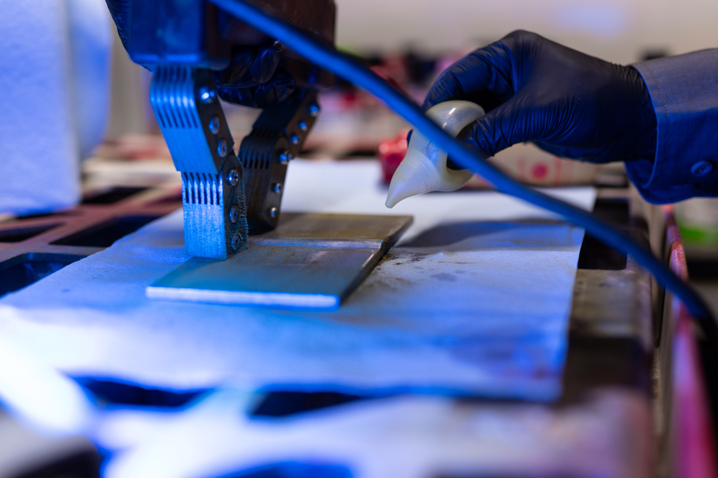
Magnetic Particle
Magnetic particle testing (MPT) is a highly effective method for detecting and evaluating stress corrosion cracking (SCC) during pipeline direct assessment activities. Using the magnetic particle black-on-white method with an AC yoke, this technique ensures reliable identification of suspect areas.
As part of NDT and Inspection services, magnetic particle testing plays a critical role in maintaining pipeline integrity by providing accurate and efficient detection of surface and near-surface discontinuities. This method supports compliance with ASME Code requirements and enhances the safety and reliability of piping and vessel fabrication facilities.
PIPELINE INTEGRITY
Pipe to Soil Potential
Pipe to soil potential measurements are a critical component of assessing the performance of cathodic protection (CP) systems and detecting anomalous conditions along underground, coated pipelines. This method evaluates the effectiveness of impressed current cathodic protection, which introduces an electrical current into the pipeline to suppress anodic activity and minimize corrosion. Another protection method involves connecting the pipeline to a sacrificial anode, such as magnesium or zinc, which corrodes in place of the protected metal.
As part of NDT and Inspection services, pipe to soil potential measurements ensure compliance with ASME Code requirements and support the integrity of piping and vessel fabrication facilities, safeguarding pipeline systems against corrosion.
Applications for Pipe to Soil Potential
- Measures cathodic protection (CP) potential in a specific area
- Detects issues with CP systems, enabling clients to make necessary adjustments
Here are some advantages of Pipe to Soil Potential
- An established method for evaluating the effectiveness of cathodic protection
- Helps locate potential corrosion areas in the pipeline, indicated by current flow from the pipe to the soil
- Provides valuable data to determine the presence of corrosion in specific pipeline areas
PIPELINE INTEGRITY
Soil Resistivity
Soil Resistivity measures the conductivity of the soil surrounding a pipeline and is a critical factor in pipe-to-soil potential assessments. Since cathodic protection (CP) introduces an electrical current between the pipe and the soil, soil resistivity determines how much the soil resists the flow of electricity. Identifying areas of lowest soil resistivity is essential when designing extensive grounding systems to achieve the most economical and effective installation. Typically, lower resistivity indicates a higher potential for corrosion.
Field measurements of soil resistivity are conducted using a specially designed probe inserted into the ground near the underground pipeline. These measurements provide valuable data, enabling clients to make necessary adjustments to protect pipelines and ensure compliance with ASME Code requirements.
Moisture Content Affects Soil Resistivity
Moisture content is a significant factor in soil corrosivity, along with other variables. Water is a key element in the electrochemical corrosion process, alongside metal and oxygen. In completely dry soil, corrosion cannot occur. Studies show that higher moisture content reduces soil resistivity, increasing the potential for corrosion. However, once the soil reaches its saturation point, additional moisture has little to no effect on resistivity.
Applications for Soil Resistivity
- Measures the conductivity of the soil
- Determines soil resistivity to adjust cathodic protection (CP) as needed
PIPELINE INTEGRITY
Coating Inspection
Coating Inspection is a critical direct visual inspection performed by highly trained technicians to assess the condition of existing pipeline coatings. This inspection is essential every time a pipeline is exposed, as coatings serve as the first line of defense against external damage and work in tandem with cathodic protection (CP) systems to prevent corrosion.
During the inspection, technicians meticulously record the condition of the coating or wrap, noting key features such as disbonded areas, blisters, discoloration, wrinkles, missing sections, or tears. These observations are vital for accurately assessing the coating’s condition and ensuring the pipeline’s integrity.
As part of NDT and Inspection services, coating inspection ensures compliance with ASME Code requirements and supports the safety and reliability of piping and vessel fabrication facilities, safeguarding pipelines from external damage and corrosion.
ADVANCED NDT
Time of Flight Diffraction (TOFD)
TOFD is an advanced ultrasonic method ideal for weld examination and defect monitoring in pipelines. This technique offers high accuracy for sizing and detecting cracks, ensuring compliance during infrastructure inspections.
The Time of Flight Diffraction (TOFD) method uses a pair of angle-beam L-wave ultrasonic probes that are used in a pitch-catch configuration with the sound beam passing through the area of interest. A transmitter probe emits an ultrasonic pulse which is picked up by the receiver probe on the opposite side. In an undamaged part, the signals picked up by the receiver probe are the result of multiple different wave energies that were generated by the transmitted beam: one that travels along the surface (lateral wave) and L-wave that reflects off the inside surface (back-wall reflection), and one S-wave that reflects off the inside surface. When a discontinuity such as a crack is present, there is a diffraction of the ultrasonic sound wave from the top and bottom tips of the crack. Using the measured time of flight of the transmitted and diffracted energy responses, the height and depth of the flaw can be calculated.
Applications for Time of Flight Diffraction
- Detecting cracking and sizing cracks as well as other planar defects, e.g. lack of fusion
- In-service defect monitoring and detecting manufacturing defects
- Weld examination – for pressure vessels, piping and storage tanks and spheres; in-service and new construction examinations
- Flaw growth monitoring and discrimination of defects between weld overlay, clad and base metal
- Measuring wall loss at welded joints damaged by preferential corrosion/root erosion
Time of Flight Diffraction UT Testing Advantages
- Very fast and effective scanning welded joints (new construction and in service)
- Position and size data for every flaw can be compared for repeat scans of the same areas to track flaw growth or corrosion rates
- Can also be used for in-service defects, such as cracking, corrosion, erosion, etc.
- Measuring wall loss at welded joints is typically more effective with TOFD than with angle-beam pulse-echo methods
Limitations of Time of Flight Diffraction
- Weld must be accessible from both sides
- Gathers and displays information in a way that requires experience to interpret
- Not always code accepted as a stand-alone inspection technique
PIPELINE INTEGRITY
Soil pH
Soil pH measures the acidity or alkalinity of the soil, typically ranging from 2.5 (acidic) to 10 (alkaline). A neutral pH of 7 is ideal for minimizing the risk of corrosion, while pH levels of 5 or below significantly increase the potential for corrosion and premature pitting in steel and metallic structures. Factors such as rain, climate, mineral content, and organisms can influence soil pH, making it a critical parameter in pipeline direct assessment.
Similar to soil resistivity, soil pH measurements are conducted using a specially designed probe inserted into the ground near the underground pipeline. These measurements provide valuable data for evaluating cathodic protection (CP) performance and making necessary adjustments to safeguard pipelines.
Applications for Soil pH:
- A vital component of pipeline direct assessment
- Helps clients adjust cathodic protection (CP) by determining soil pH and resistivity
As part of NDT and inspection services, soil pH testing supports the integrity of piping and vessel fabrication facilities, ensuring pipelines are protected from corrosion and maintaining long-term operational reliability.
PIPELINE INTEGRITY
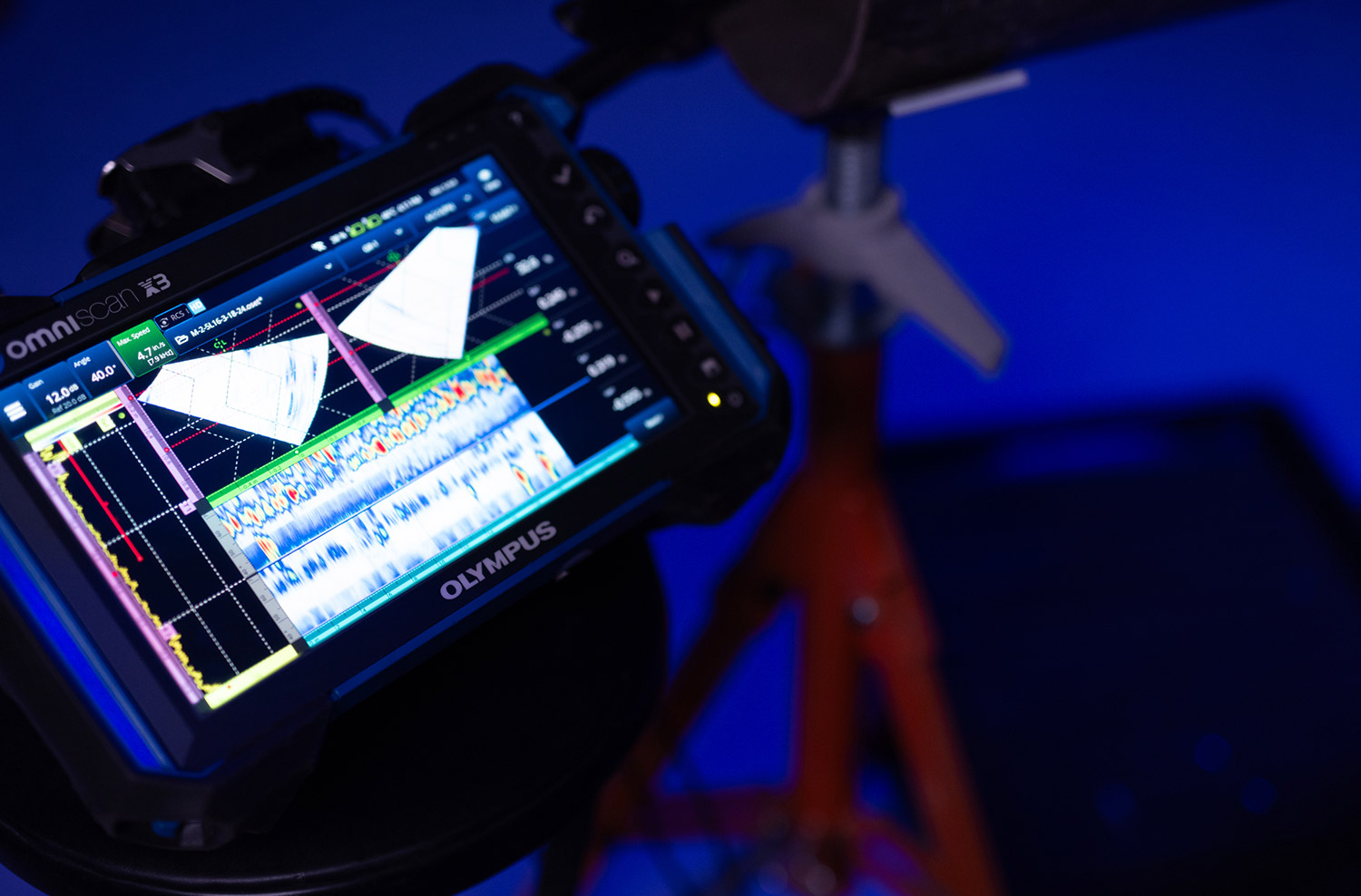
Phased Array Ultrasonic
Phased array ultrasonic testing (PAUT) is an advanced NDT and inspection service that offers superior detection and sizing capabilities compared to conventional manual ultrasonic testing (UT). During pipeline direct assessment activities, PAUT is invaluable for evaluating corrosion at welds, stress corrosion cracking (SCC), and other anomalies, providing the critical data needed for informed decision-making.
As part of NDT and Inspection services, phased array ultrasonic testing (PAUT) ensures compliance with ASME Code requirements and delivers precise, reliable results for maintaining the integrity of piping and vessel fabrication facilities.
Applications for Phased Array Ultrasonic Testing (PAUT)
- Weld evaluation for flaws such as lack of fusion, porosity, slag inclusions, and incomplete penetration
- Volumetric inspection of forging or casting materials
- Mapping erosion and corrosion activity, including material loss, pitting, and root erosion
- Profiling remaining wall thickness in corrosion surveys (when surface condition and geometry allow)
- Detecting environmentally or process-induced damage, such as microbiologically-influenced corrosion (MIC), hydrogen induced cracking (HIC), thermal fatigue cracking, caustic cracking, and SCC
Flaws that Phased Array can detect
- Weld flaws such as lack of fusion, slag inclusions, porosity, connection of surface and/or embedded cracks, and incomplete penetration
- Erosion or corrosion – material loss, pitting, and root erosion
- Inherent discontinuities in forged or casting materials such as laminations, forging bursts, cavity defects, cold shuts, hot cracking and inclusions
- Environmentally or process induced damage such as Microbiologically-Influenced Corrosion (MIC), Hydrogen Induced Cracking (HIC), thermal fatigue cracking, caustic cracking and stress corrosion cracking
Advantages of Phased Array Ultrasonic Testing
- Multiple display formats (e.g., cross-sectional, plan view, end view) enhance flaw detection and analysis
- Data can be captured, stored, and replayed for future reference and inspections
- Advanced analysis software enables additional processing and visualization of inspection data
- Effective for a wide range of industries, including oil and gas, petrochemical plants, power generation, and chemical industries, especially for new construction of piping, pipelines, vessels, and structural welded materials
Limitations of Phased Array
- Requires accessibility to a clean, smooth surface for optimal results
- Coarse-grained materials and exotic alloys may attenuate PAUT energy, similar to conventional UT
PIPELINE INTEGRITY
Entrapped Water pH
Entrapped water pH measures the alkalinity of water trapped beneath disbonded coatings on pipelines. Alkalinity reflects the water's capacity to resist changes in pH that could make it more acidic. To fully assess the corrosiveness of entrapped water, both its alkalinity and pH must be measured.
Water with a pH below 6.5 is generally acidic, soft, and corrosive. Acidic water often contains elevated levels of toxic metals such as iron, manganese, copper, lead, and zinc, which can accelerate corrosion and cause early damage to metal piping. This makes Entrapped Water pH testing a critical component of pipeline direct assessment.
The pH of entrapped water is determined by inserting a litmus strip into the water to measure its pH level. This data provides pipeline companies with valuable insights to take necessary precautions and ensure the safety and integrity of their pipelines.
As part of NDT and Inspection services, entrapped water pH testing supports compliance with ASME Code requirements and helps maintain the long-term reliability of piping and vessel fabrication facilities.
Why Choose XCEL for Pipeline Integrity?
Trusted Expertise
Our team includes top-tier professionals certified in NDT auditing, NDT procedure development, and advanced NDT methods like phased array ultrasonics and coating inspections.
Comprehensive Solutions
From facility shutdown support to pipe field services, we provide comprehensive solutions to address your unique operational challenges.
Cutting-Edge Technology
We offer the most advanced tools and techniques, including digital radiography, real-time radiography, and guided wave ultrasonics, backed by decades of industry experience.
Efficiency and Accuracy
Our advanced methods reduce inspection time, increase reliability, and seamlessly integrate with your compliance and maintenance schedules.
Industries We Serve
Our advanced NDT services ensure safety, performance, and compliance across industries, including:
- Petrochemical – Refineries, vessels, and structural components.
- Power Generation – High-energy, critical infrastructure inspections.
- Pipeline – Comprehensive direct assessments for compliance and maintenance.
- Manufacturing – Improved quality and integrity for products and equipment.