Pipeline Integrity
As the name implies, pipeline integrity is about the actions required to ensure our pipeline systems continue to operate safely and efficiently.
At XCEL, we strive to provide our clients with the most accurate and reliable pipeline direct assessment examinations, from SmartPig follow-up and anomaly verifications, to basic pipe evaluations. We can provide streamlined reporting tailored to meet each customers’ needs and diligently maintain our commitment to customer satisfaction. Both conventional and advanced NDT methods, as well as those activities specific to pipeline direct assessment are available.
- UT SHEARWAVE
- LASER MAPPING
- POSITIVE MATERIAL IDENTIFICATION
- UT THICKNESS
- AUT CORROSION MAPPING
- VISUAL
- MAGNETIC PARTICLE
- PIPE TO SOIL POTENTIAL
- SOIL RESISTIVITY
- COATING INSPECTION
- TIME OF FLIGHT DIFFRACTION
- SOIL pH
- PHASED ARRAY ULTRASONIC
- ENTRAPPED WATER pH
PIPELINE INTEGRITY
UT SHEARWAVE
Ultrasonic shearwave (UTSW)testing is a crucial tool in pipeline integrity direct assessments, providing reliable and accurate data to ensure the safety and longevity of pipeline systems. Its non-destructive nature and ability to detect various types of flaws make it an essential technique in the maintenance and monitoring of pipelines.
This technique utilizes high-frequency sound waves to detect, measure, and characterize sub-surface and surface breaking flaws.
Applications for Ultrasonic Shearwave Testing (UTSW):
- Weld evaluation
- Detecting/characterizing internal corrosion, pitting,or other internal mill related defects such as inclusions, lack of weld fusion, etc.
- Long seam evaluation
- Stress Corrosion Cracking (SCC) evaluation
PIPELINE INTEGRITY
LASER MAPPING
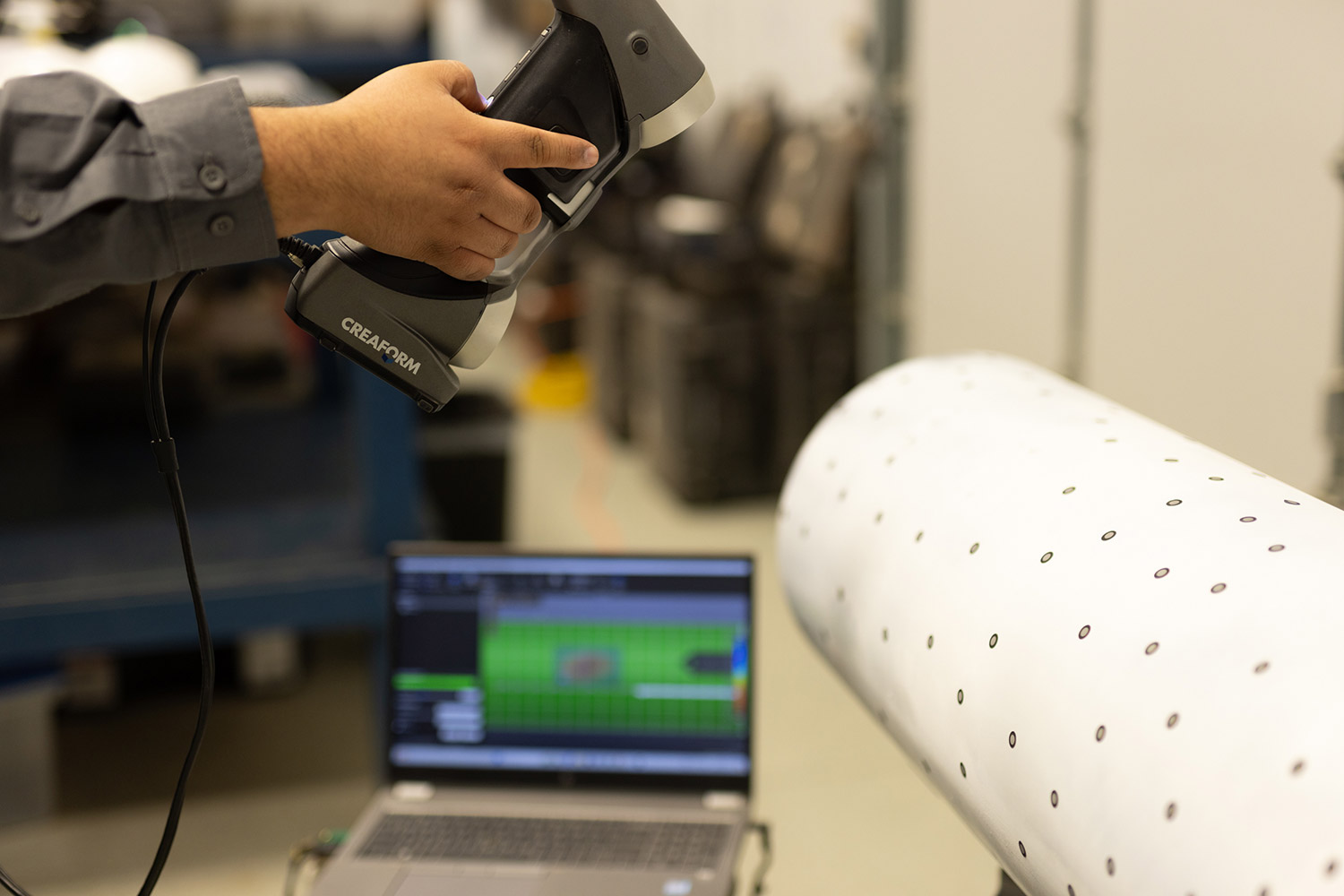
Laser Profilometry often referred to simply as "Laser Mapping" provides surface detail and measurement at accuracies and coverage levels simply not achievable through normal, mechanical means. It also allows accurate measurements on contoured surfaces, e.g. fittings, saddles, etc. where physical measurement results are difficult if not impossible to achieve without exceptional effort.
Laser Mapping is a non-contact, nondestructive technology that digitally captures the shape of physical objects using lasers. Reflector dots are placed all around the object for orientation reference points. The lasers reflect off the dots capturing a physical object’s exact surface characteristics and complexion and converts it into a digital 3-dimensional representation.
Creaform Portable 3D Laser Mapping Scanner
The Creaform handy scanner offers the fastest solution on the market for data acquisition and with help from the Pipecheck offered with the scanning system, we can also boast the fastest analysis and report turn arounds. The Creaform scanner covers the accuracy, simplicity, portability and traceability that clients demand in a competitive market.
Pipecheck has corrosion software that utilizes ASME B31, B31G, B31G Modified, and Effective Area Method to evaluate a pipeline’s fitness for service in a fast and reliable way. Here are the key features offered with the Corrosion software.
Key Features
- Interaction rules automatically applied
- Burst pressure calculations (ASME B31G, B31G Modified and Effective Area methods)
- Worst-case-profile and customizable grid resolution for all features
- Feature dimensions (length and width) and maximum depth extracted for all features
- Snipping tool for additional reporting information
- Assessment performed on internal and external surface of the pipeline or on the true wall thickness
- 3D and 2D colormap with river-bottom path overlay.
- 2D profile section in both axial and circumferential direction
- Quick, on-the-fly depth analysis: simply hover the mouse over each point to obtain local material loss.
Pipecheck Mechanical damage software analyzes mechanical damage, such as dents, gouges and other localized surface deformations. Here are the key features offered with the mechanical damage software.
Key Features
Depth-Based Assessment Type
- Automatic maximum depth measurement using straight edge technique in both directions
- 3D and 2D depth colormaps
- Automatic 3D cross-section creation
- Depths over diameter ratio
- Snipping tool for additional reporting information
- Depths extracted from Creaform’s virtual pit gauge tool
- Maximum diameter found at 90 degrees of the dent
Key Features
Strain-Based Assessment Type
- Automatic maximum strain detection
- 3D and 2D strain colormap (all strain components)
- Results for decomposed values: circumferential bending, longitudinal bending, longitudinal extensional, effective strain on inside and outside surface of the pipe as well as maximum effective strain value.
PIPELINE INTEGRITY
POSITIVE MATERIAL IDENTIFICATION
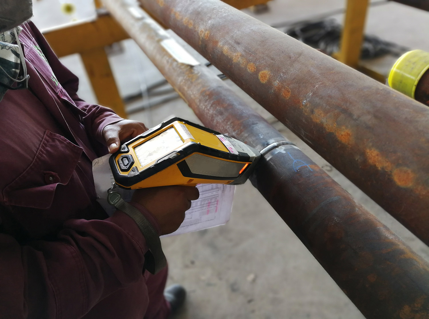
PMI is used extensively to sort or identify materials and fittings to ensure fitness for purpose.
Positive Material Identification (PMI) is a method used to analyze the chemical composition of metals and alloys. This method is a vital part of production and asset integrity management programs across industries such as oil and gas, power, petrochemical, nuclear and fabrication.
PMI can be used to verify that a fitting, pipe or other material actually possesses the elements required for it’s particular material specification. Installing incorrect material in a system can lead to premature or even catastrophic failures.
Positive Material Identification is performed using one or more of the techniques below:
- Optical Emission Spectroscopy (OES): This method covers the analysis of chemical elements including carbon, lighter silica and other lighter elements. The older OES equipment is portable but can vary in weight and size. Newer technology advancements are allowing the OES systems to become more portable and durable similar to the XRF handheld systems.
- X-Ray Fluorescence (XRF) analyzer: This is the most common method as the portable hand-held equipment allows the PMI to be done on-site. The handheld analyzer determines the elemental composition of the material. However, it cannot detect carbon and some lighter elements.
- Laser Induced Breakdown Spectroscopy (LIBS) is the portable “OES” instrument that we commonly use for Carbon Equivalency (CE). This portable unit uses a consumable argon cartridge integrated into the instrument.
Positive Material Identification application includes
- Verifying chemical composition of metals and alloys
- Detecting misidentified alloys
- Verifying material meets the code standard and specification (both customer and industry)
- Confirming welded components were made using the correct filler material
Advantages of PMI
- Quick and accurate analysis
- Highly portable hand-held digital technology
Limitations of PMI
- The depth of penetration of the x-ray for most elements is less than 0.001” so the technician must determine if the area being examined is representative of the entire piece.
- The surface of the item must be accessible and surface preparation may be needed
- Analyzers are limited to identifying only those alloys that are listed in the manufacturer’s library
- Carbon, sulfur and phosphorous cannot be identified with XRF method
- The instrument must be able to maintain surface contact with the material
PIPELINE INTEGRITY
ULTRASONIC THICKNESS TESTING
Ultrasonic Straight Beam and other ultrasonic NDT flaw detection techniques utilize sound energy in the testing procedure.
Straight beam testing utilizes the concept that sound energy traveling through a medium will continue to propagate until it either disperses or reflects off a boundary of another material. Air surrounding a far wall or the gap created by a flaw or like discontinuity are examples of material that causes reflection of the sound energy. In this type of test, the operator pairs the transducer to the test piece and identifies the echo returning from the far wall (known as ‘the backwall signal’). After identifying the backwall signal location on a good part, the operator then looks for any additional echoes that appear ahead of the said signal or watch for the signal to shift when inspecting a test piece. An acoustically significant echo that precedes the backwall signal may represent the presence of a laminar crack or void. Through further analysis, the depth, size, and shape of the structure producing the reflection can be determined.
Normal/Angle Beam
Normal beam testing uses a sound beam that is introduced at 90 degrees to the surface – for thickness testing, while angle beam utilizes a beam that is introduced into the specimen at some angle other than 90 degrees. The choice between the two is made based on the orientation of the discontinuities that are of interest to the inspector, as the inspector should always try to introduce the sound beam at an angle as close to perpendicular the discontinuities primary axis so that the maximum amount of sound reflection occurs.
Applications for Ultrasonic Straight Beam Testing
- Flaw detection such as parallel cracks, inclusions, porosity, laminations, etc
- Erosion/Corrosion thickness gauging and mapping
- Assessment of bond integrity
Advantages of Ultrasonic Straight Beam Testing
- Detects surface and subsurface discontinuities
- Superior representation of depth of penetration vs. other test methods
- With a pulse-echo technique, only one sided access is required
- Accurately estimating discontinuity size and shape
- Minimal surface prep is needed
- Immediate results produced by using electronic equipment
- It can be automated. Automated testing results in detailed images
Limitations of Ultrasonic Straight Beam Testing
- Surface must be accessible
- Requires couplant to promote sound transfer
- Surface roughness, certain castings, or exceptionally thin materials are difficult to inspect
- Linear defects oriented parallel to the sound beam go undetected
PIPELINE INTEGRITY
AUT CORROSION MAPPING
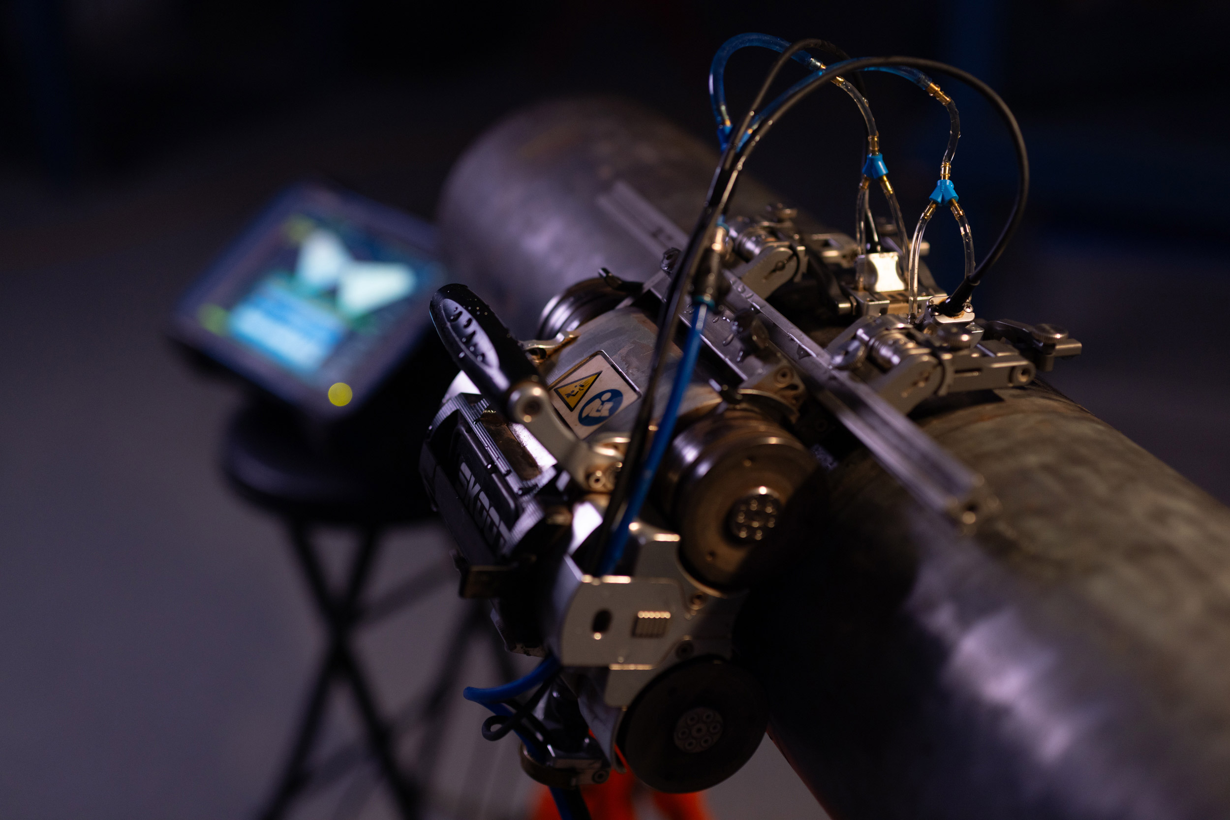
AUT Corrosion Mapping has become an essential tool for gathering accurate, detailed thickness and topography data during the direct assessment phase of pipeline integrity operations. As indicated in it's name it literally produces a plan view "map" of the examination area with thickness values depicted in a colorized format that readily displays areas of corrosion and/or erosion.
Automated Ultrasonic Testing (AUT) Corrosion Mapping plots the opposite surface of pressure vessels, piping, tanks, heat exchangers, and more. This is critical to determine not only the remaining thickness but the topography and area affected. Access to only one side is needed so the underside of a tank floor can be examined from inside the tank, the ID surface of a piping system can be mapped from the outside surface, etc. The systems are capable of acquiring actual wall thickness over large areas of test subjects while the system is on or off-line. AUT Corrosion Mapping is also used for remaining life determinations as prescribed by the facility’s Mechanical Integrity program.
Applications for AUT Corrosion Mapping:
- Opposite side corrosion, pitting, and erosion
- Mid-wall or sub-surface indications like laminations, inclusions, and blisters
- Locate and detect Hydrogen induced cracking (HIC) and blisters
Advantages of AUT Corrosion Mapping include
- High degree of repeatability
- Location and dimension data for every discontinuity can be compared for repeat scans in the same location. These comparison reports highlight specified area flaw growth or corrosion rates as well as individual discontinuities.
- Creates a top down (C-scan) visual illustration of damage as well as a side view (cross sectional) visual illustration of damage
- Encoded scanning allows for a large amount of data to be captured in a very short time.
Limitations of AUT Corrosion Mapping include
- Accessibility of area that needs inspected
- Surface cleanliness and roughness of part that needs inspected
- Tracks or magnetic strips may be needed for stainless or other nonmagnetic surfaces
PIPELINE INTEGRITY
VISUAL TESTING
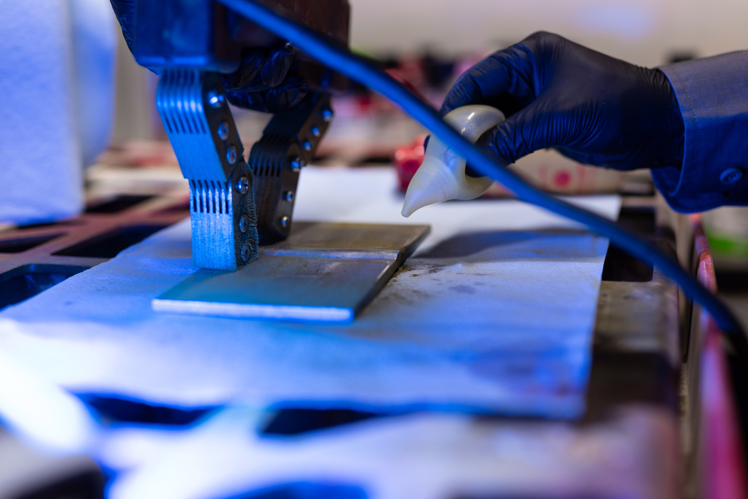
Visual examination by a trained, experienced individual cannot be oversold as a necessary component of any direct assessment effort. Many conditions are detected through initial visual examination that require additional investigation to determine the extent and severity of the condition. XCEL has personnel experienced in the evaluation of pipelines during direct assessment activities.
Visual examination is the backbone of any inspection effort and is critical to pipeline integrity. Properly trained and equipped personnel ensure the highest level of scrutiny when examining your pipelines and facilities. See our Conventional Services page for more information.
PIPELINE INTEGRITY
MAGNETIC PARTICLE TESTING
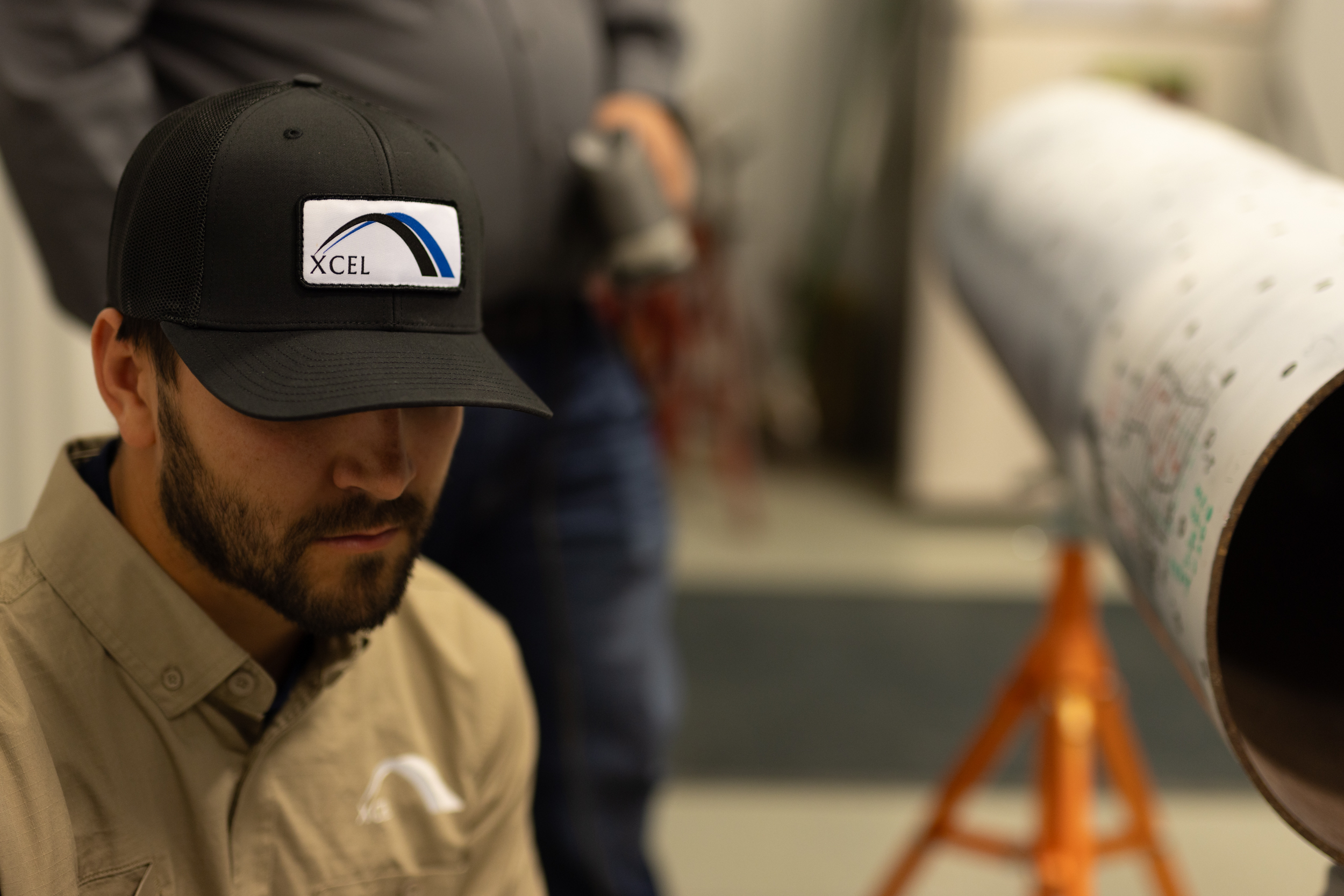
During pipeline direct assessment activities, the detection and evaluation of Stress Corrosion Cracking (SCC) is a primary concern. Examining suspect areas using Magnetic Particle Black-on-White method with an AC yoke has proven to be very effective.
PIPELINE INTEGRITY
PIPE TO SOIL POTENTIAL
Pipe to Soil Potential measurements are important for assessing the performance of cathodic protection (CP) systems and detection of certain types of anomalous conditions along underground, coated pipelines. Impressed current cathodic protection uses an electrical current that is introduced into the pipeline to suppress anodic activity and arrest or minimize corrosion activity. Another method of protection connects the metal to be protected (pipeline) to a more easily corroded ‘sacrificial anode’ such as magnesium (mag bag) or zinc to act as the anode. The sacrificial anode then corrodes instead of the protected metal.
Applications for Pipe to Soil Potential
- Measures Cathodic Protection (CP) potential in an area
- Detects specific problems with CP so client can make alteration
Here are some advantages of Pipe to Soil Potential
- Pipe to Soil Potential is an established method for measuring the effectiveness of cathodic protection.
- Measurements of pipe to soil potential are helpful in the location of possible corrosion areas in the pipeline. The corrosion areas are indicators of current flowing from the pipe to the soil.
- Provides useful data to assist the client in determining the presence of corrosion in the pipeline in that area.
PIPELINE INTEGRITY
SOIL RESISTIVITY
Soil resistivity measures the conductivity of the soil around the pipeline. The soil resistivity is a critical factor for pipe-to-soil potential. Cathodic protection introduces an electrical current between the pipe and the soil so the soil resistivity measures how much the soil resists the flow of electricity. When designing an extensive grounding system, it is advisable to locate the area of lowest soil resistivity in order to achieve the most economical grounding installation. Typically, the lower the resistivity the higher the corrosion potential.
Field soil resistivity measurements are taken with a specially designed probe that is inserted into the ground near the underground pipeline. The soil resistivity helps clients make any adjustments needed to protect the pipelines.
Moisture Content Affects Soil Resistivity
The moisture content in the soil is a large factor in soil corrosivity along with other variables. Water is considered one of the major elements needed for the process of electrochemical corrosion, along with other components such as metal and oxygen. Essentially, if the soil is totally dry, corrosion won’t happen. According to various studies, higher moisture content can reduce the soil resistivity, which can in turn increase the potential for corrosion. However, when the soil has reached its saturation point, extra moisture will have little or no effect on the resistivity.
Applications for Soil Resistivity
- Measures the conductivity of the soil
- Determines soil resistivity so cathodic protection can be adjusted as needed
PIPELINE INTEGRITY
COATING INSPECTION
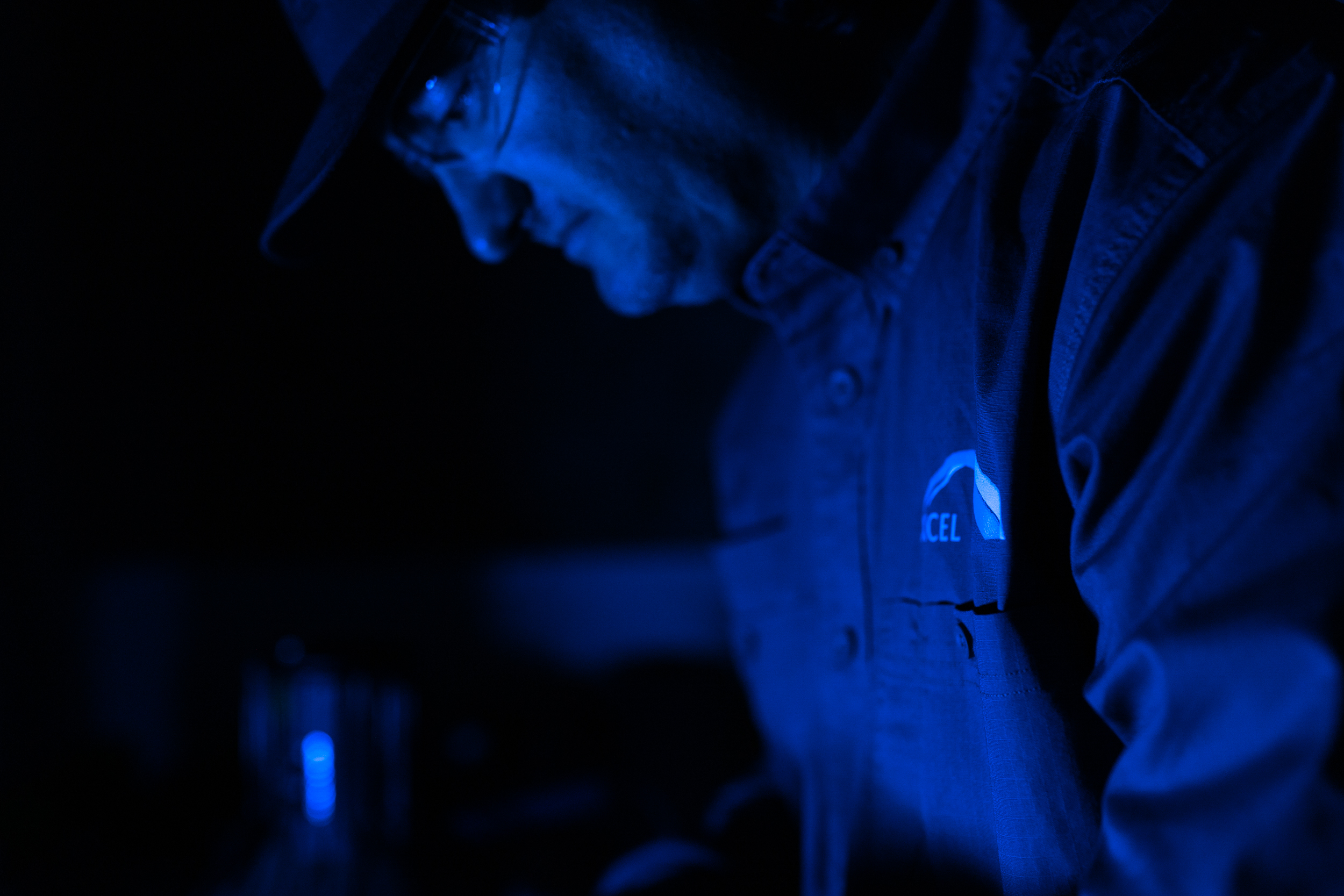
Inspection of existing coatings is a direct visual inspection performed by highly trained technicians. This is an important inspection that should be performed every time the pipeline is exposed. During the visual inspection, the technician records the condition of the coating or wrap noting features like: disbonded areas, blisters, discoloration, wrinkled, missing, torn, etc. are paramount and recorded when assessing coating condition. Pipeline coatings work in concert with cathodic protection and are the first line of defense against external damage.
ADVANCED NDT
TIME OF FLIGHT DIFFRACTION
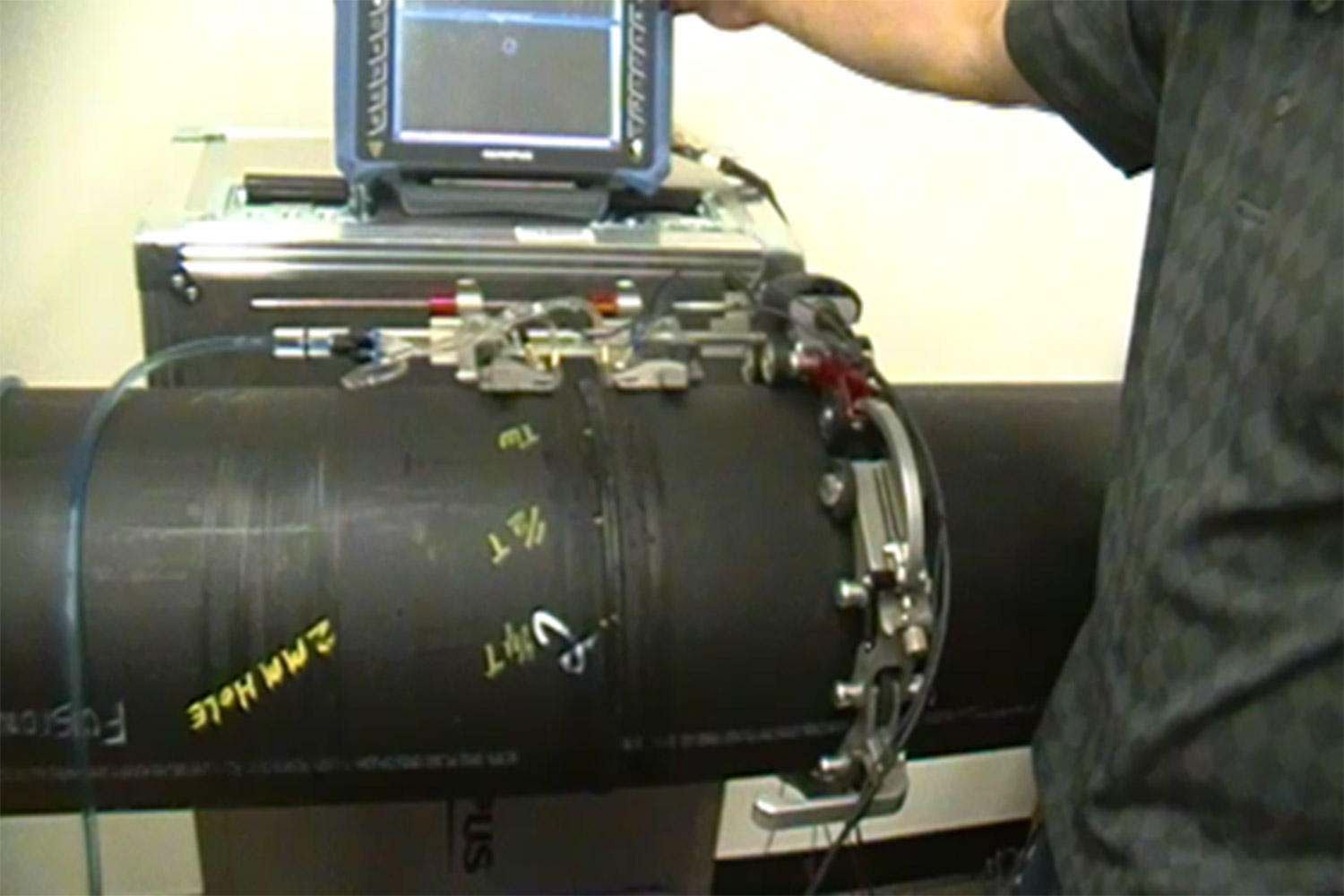
Time-of-flight diffraction (TOFD) method of ultrasonic testing is an effective and reliable weld testing procedure. Due to the use of difffracted signals as opposed to reflected signals it is a valuable complement to PAUT or as a standalone method in certain applications.
The Time of Flight Diffraction (TOFD) method uses a pair of angle-beam L-wave ultrasonic probes that are used in a pitch-catch configuration with the sound beam passing through the area of interest. A transmitter probe emits an ultrasonic pulse which is picked up by the receiver probe on the opposite side. In an undamaged part, the signals picked up by the receiver probe are the result of multiple different wave energies that were generated by the transmitted beam: one that travels along the surface (lateral wave) and L-wave that reflects off the inside surface (back-wall reflection), and one S-wave that reflects off the inside surface. When a discontinuity such as a crack is present, there is a diffraction of the ultrasonic sound wave from the top and bottom tips of the crack. Using the measured time of flight of the transmitted and diffracted energy responses, the height and depth of the flaw can be calculated.
This ultrasonic UT testing method is commonly performed on welds, weld overlay cladding, piping, pressure vessels, storage tanks, and structural steel. Fabricated vessels and piping can be thoroughly examined for fabrication flaws with Time of Flight Diffraction. Sizing of cracks and welding flaws can be done precisely using the TOFD UT testing method. Time of Flight Diffraction is also effective at measuring the remaining wall of a welded joint that has been damaged by preferential corrosion or root erosion.
Applications for Time of Flight Diffraction
- Detecting cracking and sizing cracks as well as other planar defects, e.g. lack of fusion
- In-service defect monitoring and detecting manufacturing defects
- Weld examination – for pressure vessels, piping and storage tanks and spheres; in-service and new construction examinations
- Flaw growth monitoring and discrimination of defects between weld overlay, clad and base metal
- Measuring wall loss at welded joints damaged by preferential corrosion/root erosion
Time of Flight Diffraction UT Testing Advantages
- Very fast and effective scanning welded joints (new construction and in service)
- Position and size data for every flaw can be compared for repeat scans of the same areas to track flaw growth or corrosion rates
- Can also be used for in-service defects, such as cracking, corrosion, erosion, etc.
- Measuring wall loss at welded joints is typically more effective with TOFD than with angle-beam pulse-echo methods
Limitations of Time of Flight Diffraction
- Weld must be accessible from both sides
- Gathers and displays information in a way that requires experience to interpret
- Not always code accepted as a stand-alone inspection technique
PIPELINE INTEGRITY
SOIL pH
Soil pH is the measure of the acidity or alkalinity of the soil. Soil pH typically ranges from 2.5 to 10 with 2.5 being acidic and 10 being alkaline (caustic). Corrosion potential and premature pitting in steel and metallic structures are increased when the pH level dips to 5 or below. A pH of 7, or neutral, is favorable because it can minimize the possibility of damage due to corrosion. A number of factors can affect soil pH, including rain, climate, mineral content, organisms, etc.
Like soil resistivity, soil pH measurements are taken with a specially designed probe that is inserted into the ground near the underground pipeline. Soil pH and resistivity affect cathodic protection.
Applications for Soil pH:
- Essential element of pipeline direct assessment
- By determining soil pH and soil resistivity, the client can adjust cathodic protection if needed
PIPELINE INTEGRITY
PHASED ARRAY ULTRASONIC TESTING
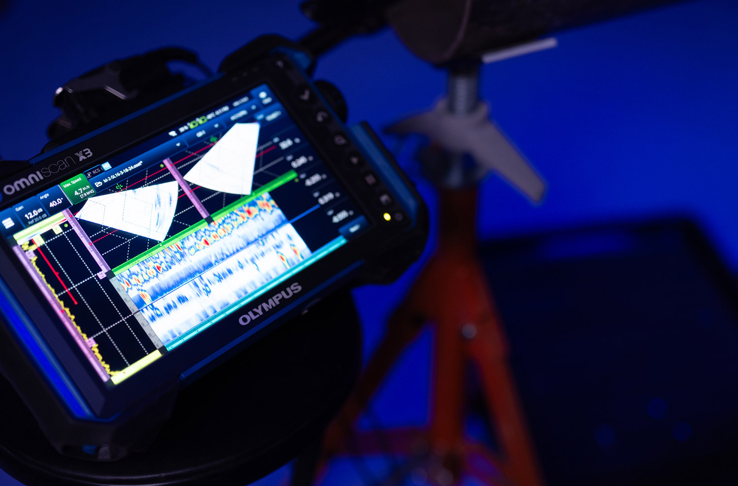
Ultrasonic Testing using Phased Arrays provides detection and sizing capabilities not normally achievable with conventional, manual UT. During pipeline direct assessment activities, the evaluation of corrosion ditching at welds, stress corrosion cracking and other anomalies is critical and often, PAUT provides the additional information needed to make an informed decision.
Phased Array for weld inspection and crack detection are the most common applications. These tests are done across a wide range of industries including oil and gas, petrochemical plants, power generation and chemical industries, especially for the construction of new piping, pipelines, vessels and structural welded materials. Phased Array can also be effectively used to profile remaining wall thickness in corrosion survey applications when surface condition and part geometry allows.
A Phased Array probe is composed of several small ultrasonic elements which are individually pulsed. By phasing the pulses across the array of elements, the ultrasonic beam can be steered and focused as needed for a particular application. Multiple beams can be generated for a single examination; therefore, a variety of beams can examine the area of interest thoroughly.
Applications for Phased Array Ultrasonic Testing (PAUT)
- Weld evaluation
- Volumetric inspection of forging or casting materials
- Mapping Erosion and corrosion activit
Flaws that Phased Array can detect
- Weld flaws such as lack of fusion, slag inclusions, porosity, connection of surface and/or embedded cracks, and incomplete penetration
- Erosion or corrosion – material loss, pitting, and root erosion
- Inherent discontinuities in forged or casting materials such as laminations, forging bursts, cavity defects, cold shuts, hot cracking and inclusions
- Environmentally or process induced damage such as Microbiologically-Influenced Corrosion (MIC), Hydrogen Induced Cracking (HIC), thermal fatigue cracking, caustic cracking and stress corrosion cracking
There are a multitude of phased array benefits due to its universal capability to perform so many inspection tasks. Here are some advantages of Phased Array
- Information can be displayed in multiple display formats (examples below), which aid in discontinuities/ flaw detection.
- Scan displays the amount of received ultrasonic energy as a function of time
- Scan displays a profile view (cross-sectional) of a specimen
- Scan displays a plan type view of the specimen & discontinuities
- Scan displays an end view of the specimen at the current position of the probe
- The data can also be captured and stored for inspector review. This also makes future reference and inspections easier.
- The replayed data can be processed and displayed in various ways using the instrument used to acquire the data or on analysis software that provides additional processing capabilities.
Limitations of Phased Array
- Accessibility to a clean smooth surface
- Material of piece being scanned. Course grained materials and exotic alloys can attenuate Phased Array UT energy the same way it will attenuate conventional UT energy and cause limitations to the inspection.
PIPELINE INTEGRITY
ENTRAPPED WATER pH
Entrapped Water pH is the measure of alkalinity in water that has become entrapped beneath disbonded coating. Alkalinity is a measure of the capacity of the water to resist a change in pH that would tend to make the water more acidic. In order to determine the corrosiveness of water, one needs the measurement of both the alkalinity and pH.
In general, water with a pH < 6.5 could be acidic, soft, and corrosive. Acidic water could contain metal ions such as iron, manganese, copper, lead, and zinc. In other words, acidic water contains elevated levels of toxic metals. Acidic water can trigger early damage to metal piping.
Entrapped water pH is determined by inserting a litmus strip into the water to determine the pH. This information is one more piece of data to help pipeline companies take necessary precautions to keep pipelines safe.


