Conventional Nondestructive Testing
Conventional NDT is commonly utilized to gather data, assess damage, ensure compliance with codes and standards, and verify critical elements of engineering design without damaging structural or functional integrity.
Conventional NDT includes methods such as film radiography, manual ultrasonics, magnetic particle testing, liquid penetrant testing, eddy current testing, visual examination and leak testing. Despite significant technological advancements, these conventional methods remain essential and often irreplaceable in many applications.
CONVENTIONAL NDT
ULTRASONIC THICKNESS TESTING
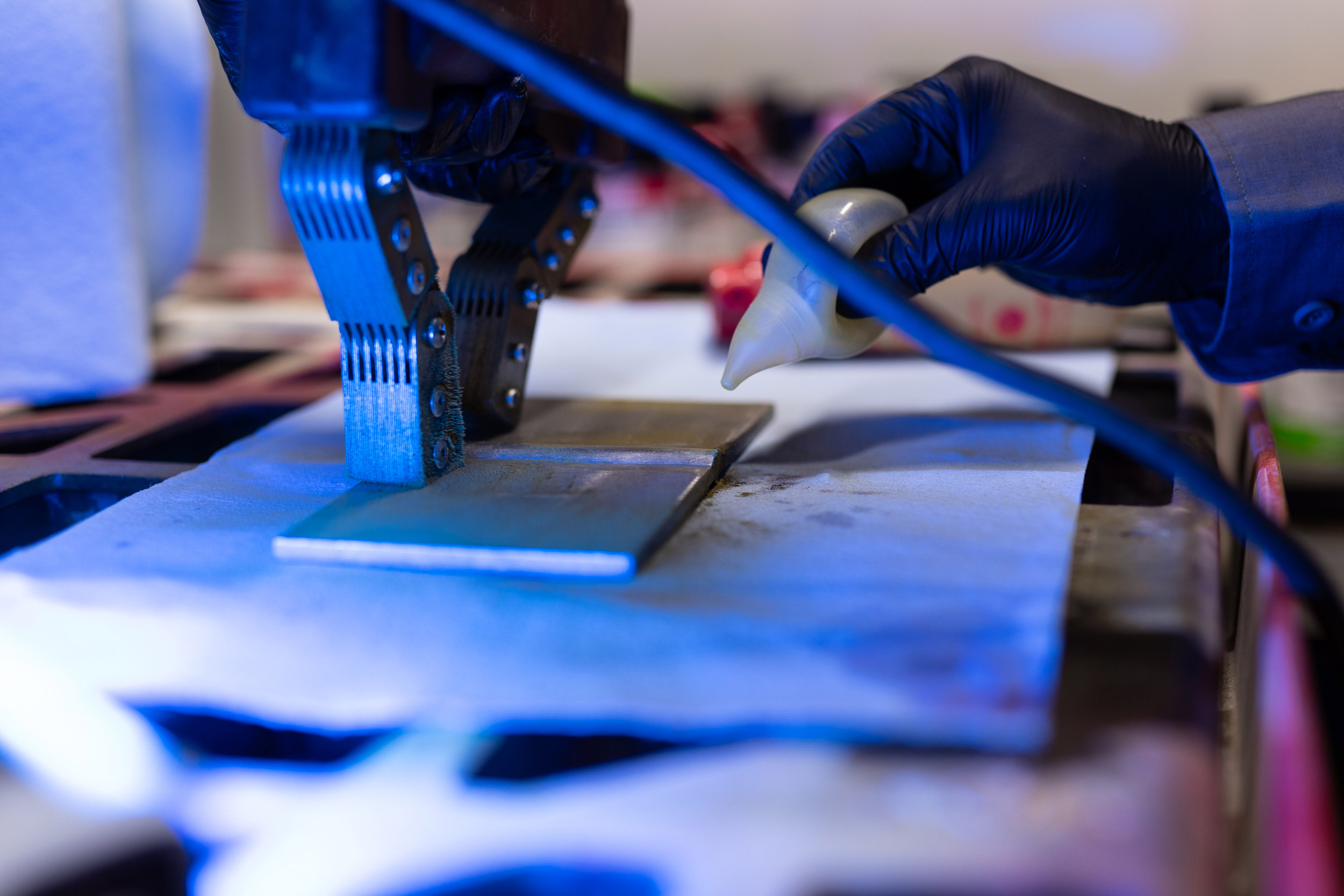
Ultrasonic Thickness Testing (UTT) provides critical information regarding the current status and remaining life of piping, tanks and vessels. Determining the thickness of a material is essential information for a number of situations.
Ultrasonic Thickness Testing utilizes high frequency sound energy to produce highly accurate thickness measurements. This technology can be utilized in one form or another in almost any environment or situation.
Two of the biggest advantages are:
- Only single sided access is required of the test piece
- Extremely accurate in the right hands and no hazards associated with the method.
CONVENTIONAL NDT
VISUAL TESTING
Visual testing (VT) is the foundation of NDT. Techniques include Direct visual, Remote visual, and Translucent viewing. Call us to discuss your visual testing needs.
Visually inspecting a part for surface imperfections is typically the first step in any examination process. Basic direct visual examination is the most elemental and cost effective inspection method when utilized properly. Remote visual systems such as video probes and camera crawlers allow visual examination in areas not normally accessible. Translucent viewing is used to examine non-metallics such as fiber reinforced plastic tanks and piping.
XCEL has personnel certified as AWS-Certified Welding Inspector (CWI), AWS Senior CWI, VT Level II and ASNT VT Level III. VT applications include but are not limited to:
- AWS-CWI/SCWI – welder qualification, weld inspection
- Mechanical Measurement – evaluation of surface conditions or dimensions using precision measuring instruments
- Condition assessment – Inspection to detect corrosion, distortion, damage and other indications of integrity loss
- Remote visual – Normally inaccessible or difficult to access areas may be accessed and examined using remote viewing equipment such as video probes, zoom cameras, crawlers, drones etc.
- Translucent viewing of FRP or other suitable items
CONVENTIONAL NDT
RADIOGRAPHIC TESTING
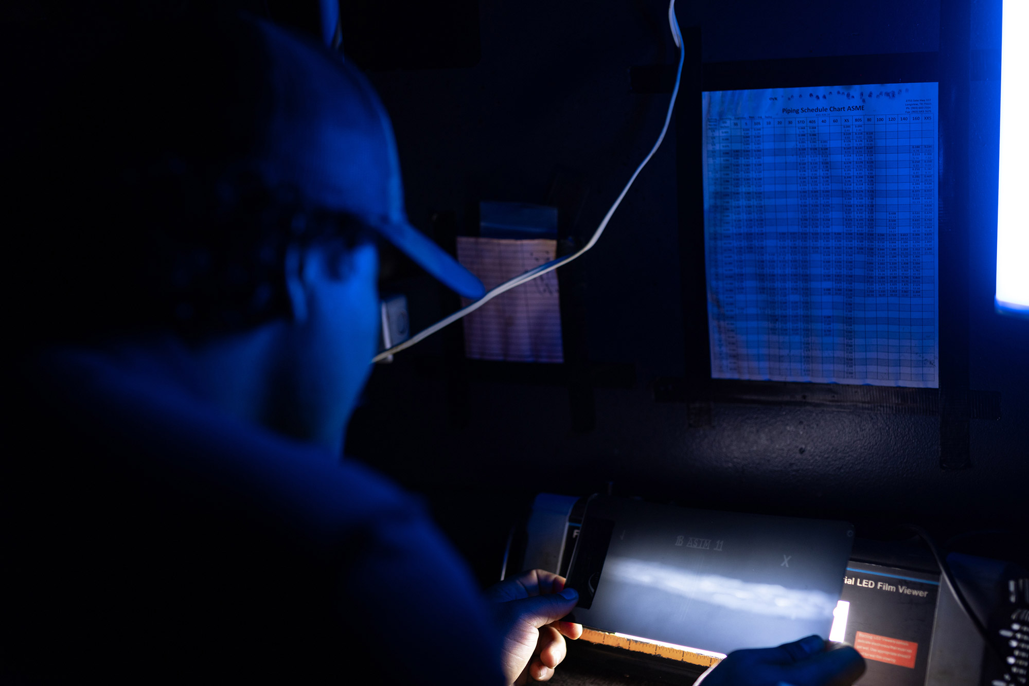
Radiographic Testing (RT) is a volumetric method that uses ionizing radiation to form images that can be used to determine quality, assess damage or simply gather information. Conventional RT using film continues to be a mainstay in the construction of pipelines, vessels, tanks and facilities.
Radiographic Testing (RT) has long been the go-to method for determining the acceptability of welds in pipelines, piping, pressure vessels, tanks and castings. RT is typically performed using either X-Rays or Gamma rays as the source of penetrating radiation. Both sources produce electromagnetic radiation, with energy and intensity being a variable. Material type, thickness, safety considerations, and shooting technique are factors in determining the type of source to be used.
Applications for Radiography
- Examination of welds, castings, forgings, and composites
- Corrosion detection and the measurement of wall thickness (profile radiography)
Advantages of Radiography
- Utilized for examination of a wide variety of material types
- Is sensitive to evident changes in thickness caused by corrosion/erosion, voids in material, certain weld flaws and to material density changes
- Detects both surface and subsurface defects
- Creates permanent record of the inspection
Limitations of Radiography
- Safety precautions are required for the safe use of radiation
- Access to both sides of the specimen is required
- Orientation of the test piece and certain flaws is critical
- Requires several steps to produce final, interpretable radiograph
CONVENTIONAL NDT
MAGNETIC PARTICLE TESTING
Magnetic Particle Testing (MT) is a nondestructive testing (NDT) method for detecting surface and shallow subsurface discontinuities in ferromagnetic materials such as iron, nickel, cobalt, and some of their alloys. Very effective for linear discontinuities such as cracking.
Magnetic Particle Testing (MT) is an effective method for detecting linear discontinuities such as cracks, seams, laps on or near the surface of ferromagnetic materials such as carbon steel, cast iron, nickel and certain alloys. Rounded indications may be detected as well but sensitivity diminishes as diameter decreases.
Magnetic Particle Testing starts by inducing a magnetic field into the object under examination. If any discontinuities or flaws are present in the object they will interrupt the magnetic field within the piece and cause an external magnetic field to be created. This external magnetic field will attract the “magnetic particles” which in turn creates an indication that is easily detected with the human eye.
The particles may be dry which can be used on clean, dry surfaces, or they may be suspended in a liquid carrier such as water or an oil-based solution depending on the technique.
Due to the visual inspection involved with this method, magnetic particles are manufactured in several highly visible colors designed to contrast with a variety of backgrounds to optimize detectability. It is very important to have magnetic particles that contrast sharply with the test surface to ensure the human eye can quickly and accurately identify all indications present. Magnetic particles are primarily used in three different forms that include:
- Dry powder – Very small iron oxide particles that are shaped elliptically and covered in a dye to provide contrast against the test surface, e.g. red, yellow, blue, gray, black.
- Black on White – In this technique, black particles are suspended in a liquid carrier and applied to a surface where a white contrast paint has been applied to optimize the contrast and therefore detectability of indications.
- Fluorescent – Very small iron oxide particles dyed with a fluorescent pigment and suspended in a liquid carrier. Fluorescent particles greatly enhance the sensitivity of the examination.
Advantages of Magnetic Particle Testing
- Quick inspection with minimal surface preparation needed compared to PT
- Detects surface and slightly subsurface flaws
- Indication of flaw is produced directly on the surface of the piece and forms a visual image of the discontinuity
- Easily portable and equipment costs are low
Limitations of Magnetic Particle Testing
- Can only be used on ferromagnetic materials e.g. carbon steel
- Limited to surface breaking or near-surface flaws
Proper alignment of magnetic field and flaw is critical
CONVENTIONAL NDT
EDDY CURRENT TESTING
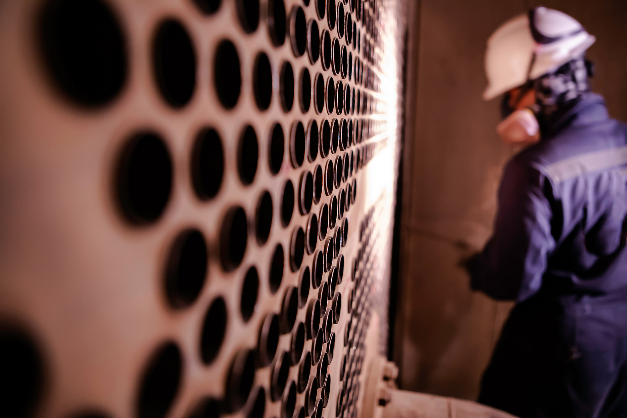
Eddy Current testing (ECT) has a wide array of applications. Depending upon the material type, form and type of flaw being sought, coils/probes used for testing may be custom made or may be shelf items. Very popular for tubing inspection (heat exchangers, etc.) it has numerous applications across the industrial/aerospace spectrum.
A part of the electromagnetic testing family, eddy current testing has become the standard examination for tubing bundles in the petro-chemical industry. It is also a mainstay of the aerospace industry to examine aircraft components for cracking or other evidence of failure.
CONVENTIONAL NDT
LEAK TESTING
Leak testing (LT) is a unique method in that it does not necessarily detect flaws, or provide quantitative information, but simply determines the effectiveness of a pressure (or vacuum) boundary based on it's ability to hold the pressure (or vacuum) without evidence of leakage or leakage beyond a specified rate (size).
Bubble leak testing (BLT) using a vacuum box is commonly used to examine tank floor welds. Direct pressure bubble leak testing is used to test valves, re-pads, and other pressure retaining equipment. Another common method is Pressure Change testing, where the item is pressurized and the pressure monitored for a prescribed period of time. Other more sensitive methods exist as well. The selection of the appropriate method and technique is critical to ensuring the proper integrity is achieved. XCEL has ASNT Level III Leak Testing personnel. Call us today to discuss your leak testing needs.
CONVENTIONAL NDT
LIQUID PENETRANT TESTING
Liquid Penetrant Testing (PT) uses specially formulated cleaners, dyes and developers to detect surface-breaking discontinuities in a wide range of materials. Commonly used on stainless steels and aluminum alloys where MT cannot be used.
When testing for surface-breaking discontinuities, Liquid Penetrant Testing (PT) is a method that can be used on aluminum, magnesium, brass, copper, high quality castings, steel, stainless steel, carbides, certain plastics and ceramics.
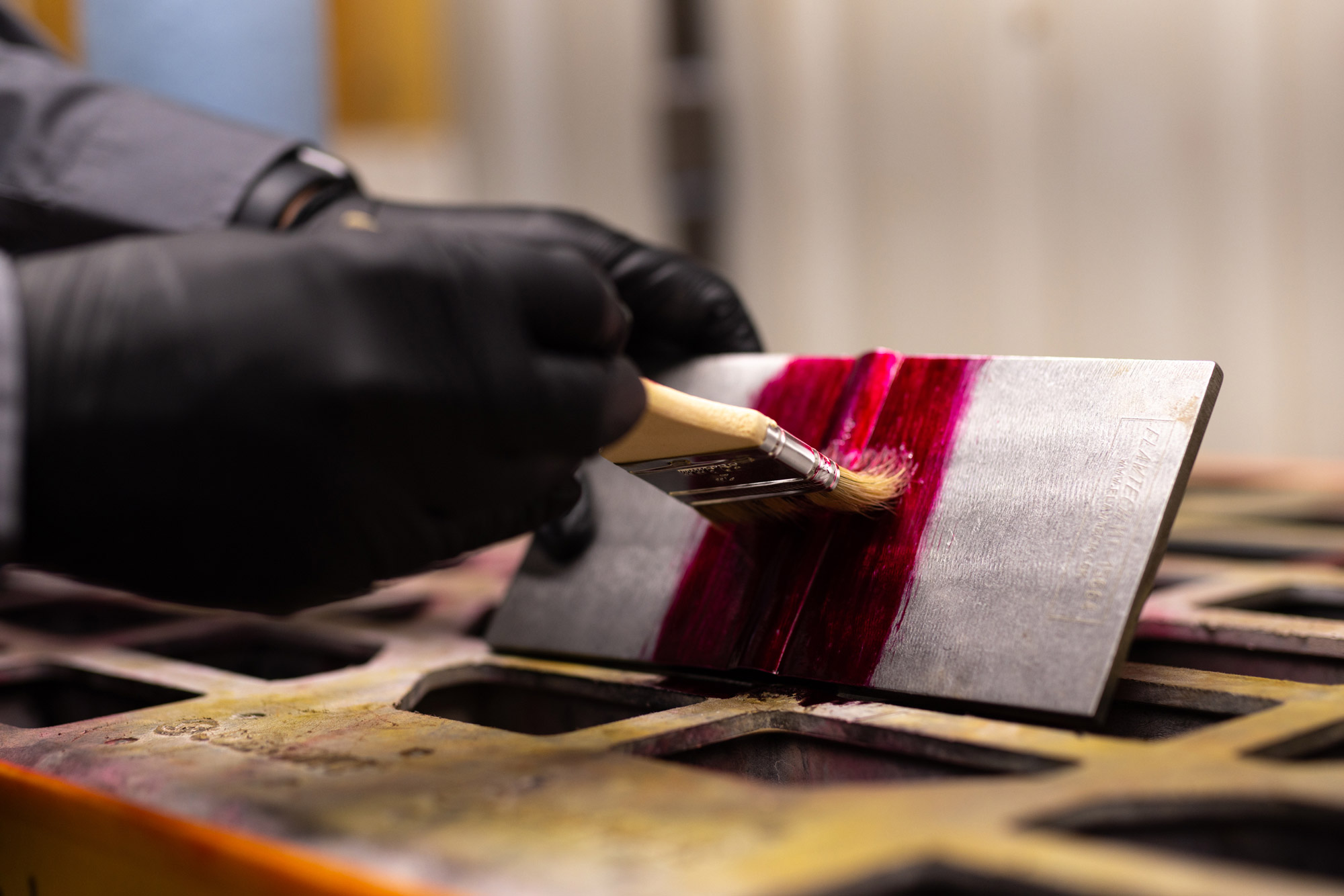
The first and most important step in penetrant testing is to preclean the test surface to be examined. After precleaning, the penetrant is applied to the surface to be tested. The penetrant, which remains in a liquid form, is attracted into surface breaking flaws by capillary action. After the penetrant is allowed to dwell on the test surface for a predetermined amount of time, the excess penetrant on the surface is removed by either water wash or solvent wipe, depending on the type used. A developer is then applied to pull any penetrant trapped in discontinuities back to the surface where it forms an indication. The developer provides a highly contrasting white background to the deep red indications produced by visible dyes or to the bright green dyes used in fluorescent dyes.
Basic Steps in Liquid Penetrant Testing:
- Precleaning
The test surface must be clean of all foreign materials. Dirt, oil, paint, rust, etc. could prevent the penetrant from properly covering the surface and entering discontinuities. Penetrant will not displace contaminants. The test piece must be completely clean and ample drying time must be allowed before applying the penetrant. - Application of the penetrant
There are two basic types of penetrants as defined by their visibility, Type I Fluorescent and Type II Visible. The types are further subdivided by the method of removal, Method A – Water Washable, Method B – Post Emulsified (Lipophilic), Method C – Solvent Removable, Method D – Post Emulsified (Hydrophilic) . All of these have their particular applications, strengths and weaknesses. Once this penetrant type is established, the penetrant is applied to the test surface in an even layer. It is very important that 100% of the area to be inspected has an adequate amount of penetrant applied to it. After the application, the penetrant is allowed to sit on the test piece for a predetermined amount of time known as dwell time. - Remove excess penetrant
Once the dwell time of the penetrant is complete, Remove the penetrant in the method prescribed for the type being used. - Apply developer
Developers are fine white powders that reverse the capillary action of discontinuities when present. The basic forms are water based, dry and non-aqueous wet. Again, the type of developer is selected based on several variables. - Inspection
Inspection of the test surface should take place immediately after the developer is applied, however the final inspection/analysis shall not be performed prior to a predetermined developing time in accordance with the applicable Code, standard or specification. If fluorescent dye is used, UV light as well as low ambient light levels would be necessary for final examination.
Defects will present contrasting “bleed out” or indications. The larger the void in the test part, the larger the indication will be. Defects such as tight cracks or lack of fusion will sometimes produce very small indications that have to be watched for closely. - Post Cleaning
The test surface may need to be cleaned after the inspection depending on the future service of the test piece.
Advantages of Liquid Penetration Testing
- Large surface areas or large volumes of parts/materials can be inspected rapidly at low cost
- Parts with complex geometry are routinely inspected
- Indication(s) are produced directly on surface of the part helping to provide a visual image and location of the discontinuity
- Non-ferromagnetic materials can be testing
Limitations of Liquid Penetration Testing
- Detects only surface breaking defects
- Surface preparation is critical as contaminants can mask defects
- Requires a relatively smooth and nonporous surface

CONVENTIONAL NDT
ULTRASONIC TESTING -
FLAW DETECTION
For years prior to the advanced techniques of PAUT and TOFD, ultrasonic flaw detection was performed using one or more combinations of UT technique variables. Contact or immersion, pulse echo or through-transmission, straight beam or angle beam. Many Codes and standards still prescribe these tried and true techniques for specific applications.
Ultrasonic flaw detection is exactly what it’s name implies. Depending on the material/item configuration, location and orientation of suspected flaws and the Code/standard/specification requirements, a technique can usually be developed to provide the required examination.
Angle beam examinations are typically performed on welds, some tubular products and forgings as prescribed. Straight beam is used to examine plate for laminations, castings, forgings, shafts and in some instances, welds.
Technology based on Results.
- Radiographic Testing (RT)
- Ultrasonic Thickness Testing (UTT)
- Leak Testing (LT)
- Visual Testing (VT)
- Magnetic Particle Testing (MT)
- Liquid Penetrant Testing (PT)
- Ultrasonic Testing – Flaw Detection
Why choose Conventional NDT?
- Gathering data
- Investigating damage
- Ensuring compliance with codes, standards and specifications
- Confirming essential elements of the engineering design
Industries that we Serve:
- Petro-Chemical
- Pulp & Paper
- Manufacturing
- Power Generation
- Fabrication
- Mining
- Pipeline
- Rail
- Ag


