Advanced Nondestructive Testing
Cutting-Edge Advanced NDT Services for Reliable Results
At XCEL, we combine innovation and expertise to deliver advanced NDE (Nondestructive Examination) solutions tailored to meet the most demanding industry requirements. Our advanced service lineup is designed to support safety, compliance, and performance across diverse industries, with a focus on precision and efficiency. XCEL is an ABS Certified Service Supplier for Nondestructive Inspection.
- AUT CORROSION MAPPING
- PHASED ARRAY ULTRASONICS
- TIME OF FLIGHT DIFFRACTION
- DIGITAL RADIOGRAPHY
- REAL-TIME RADIOGRAPHY
- GUIDED WAVE ULTRASONICS
ADVANCED NDT
AUT Corrosion Mapping
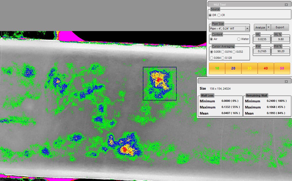
Our automated ultrasonic testing (AUT) systems provide detailed insights into wall loss, thickness, and topography. Utilizing mechanical scanners, this method is critical for the inspection of pressure vessels, piping, tanks, and heat exchangers. By offering accurate data on mechanical integrity management and remaining life assessments, AUT corrosion mapping is a vital tool for asset integrity management.
ADVANCED NDT
Phased Array Ultrasonic Testing (PAUT)
With universal applications, phased array ultrasonic testing (PAUT) is key for detecting and evaluating damages in welds, forgings, pipelines, and more. From erosion and corrosion mapping to detecting environmentally induced damage, PAUT addresses a wide range of operational challenges with precision and efficiency.
Applications for Phased Array Ultrasonic Testing (PAUT)
Applications Include:
- Weld evaluations for structural integrity.
- Volumetric inspections for cast and forged materials.
- Mapping areas affected by erosion and corrosion.
Flaws that Phased Array can detect
- Weld flaws such as lack of fusion, slag inclusions, porosity, surface and/or embedded cracks, and incomplete penetration
- Erosion or corrosion – material loss, pitting, and root erosion
- Discontinuities in forged, rolled or cast materials such as laminations, forging bursts, cold shuts, hot tears and inclusions
- Environmentally or process-induced damage mechanisms such as Microbiologically-Influenced Corrosion (MIC), Hydrogen Induced Cracking (HIC), thermal or cyclic fatigue cracking, caustic cracking and stress corrosion cracking
There are a multitude of phased array benefits due to its universal capability to perform so many inspection tasks. Here are some advantages of Phased Array:
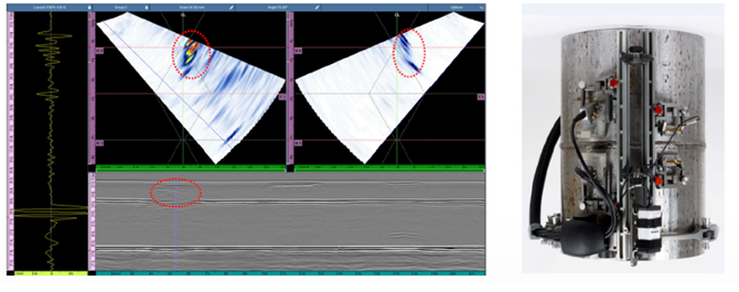
- Information can be displayed in multiple display formats (examples below), which aid in discontinuities/ flaw detection.
- A-Scan displays the amount of received ultrasonic energy as a function of time
- B-Scan displays a profile view (cross-sectional) of a specimen
- C-Scan displays a plan type view of the specimen & discontinuities
- D-Scan displays an end view of the specimen at the current position of the probe
- The data can also be captured and stored for inspector review. This also makes future reference and inspections easier.
- The replayed data can be processed and displayed in various ways using the instrument used to acquire the data or on analysis software that provides additional processing capabilities.
Limitations of Phased Array
- Accessibility to a clean smooth surface
- Material of piece being scanned. Coarse-grained materials and exotic alloys can attenuate Phased Array UT energy the same way it will attenuate conventional UT energy and cause limitations to the inspection.
ADVANCED NDT
TIME OF FLIGHT DIFFRACTION
TOFD offers a reliable and efficient method of weld testing and defect sizing. A valuable complement to PAUT, TOFD is ideal for both pipeline integrity inspections and infrastructure inspections, delivering high accuracy and repeatability in assessing material and weld conditions.
Advantages:
- Flaw growth monitoring and wall thickness loss measurement.
- Effective identification of defects in both new construction and in-service inspections.
The Time of Flight Diffraction (TOFD) method uses a pair of angle-beam L-wave ultrasonic probes that are used in a pitch-catch configuration with the sound beam passing through the area of interest. A transmitter probe emits an ultrasonic pulse which is picked up by the receiver probe on the opposite side. In an undamaged part, the signals picked up by the receiver probe are the result of multiple different wave energies that were generated by the transmitted beam: one that travels along the surface (lateral wave) and another L-wave that reflects off the inside surface (back-wall reflection), and one S-wave that reflects off the inside surface. When a discontinuity such as a crack is present, there is a diffraction of the ultrasonic sound wave from the top and bottom tips of the crack. Using the measured time of flight of the transmitted and diffracted energy responses, the height and depth of the flaw can be calculated.
This ultrasonic UT testing method is commonly performed on welds, weld overlay cladding, piping, pressure vessels, storage tanks, and structural steel. Fabricated vessels and piping can be thoroughly examined for fabrication flaws with Time of Flight Diffraction. Sizing of cracks and welding flaws can be done precisely using the TOFD UT testing method. Time of Flight Diffraction is also effective at measuring the remaining wall of a welded joint that has been damaged by preferential corrosion or root erosion.
Applications for Time of Flight Diffraction
- Detecting cracking and sizing cracks as well as other planar defects, e.g. lack of fusion
- In-service defect monitoring and detecting manufacturing defects
- Weld examination – for pressure vessels, piping and storage tanks and spheres; in-service and new construction examinations
- Flaw growth monitoring and discrimination of defects between weld overlay, clad and base metal
- Measuring wall loss at welded joints damaged by preferential corrosion/root erosion
Time of Flight Diffraction UT Testing Advantages
- Very fast and effective scanning welded joints (new construction and in service)
- Position and size data for every flaw can be compared for repeat scans of the same areas to track flaw growth or corrosion rates
- Can also be used for in-service defects, such as cracking, corrosion, erosion, etc.
- Measuring wall loss at welded joints is typically more effective with TOFD than with angle-beam pulse-echo methods
Limitations of Time of Flight Diffraction
- Weld must be accessible from both sides
- Gathers and displays information in a way that requires experience to interpret
- Not always code accepted as a stand-alone inspection technique
ADVANCED NDT
Digital Radiography
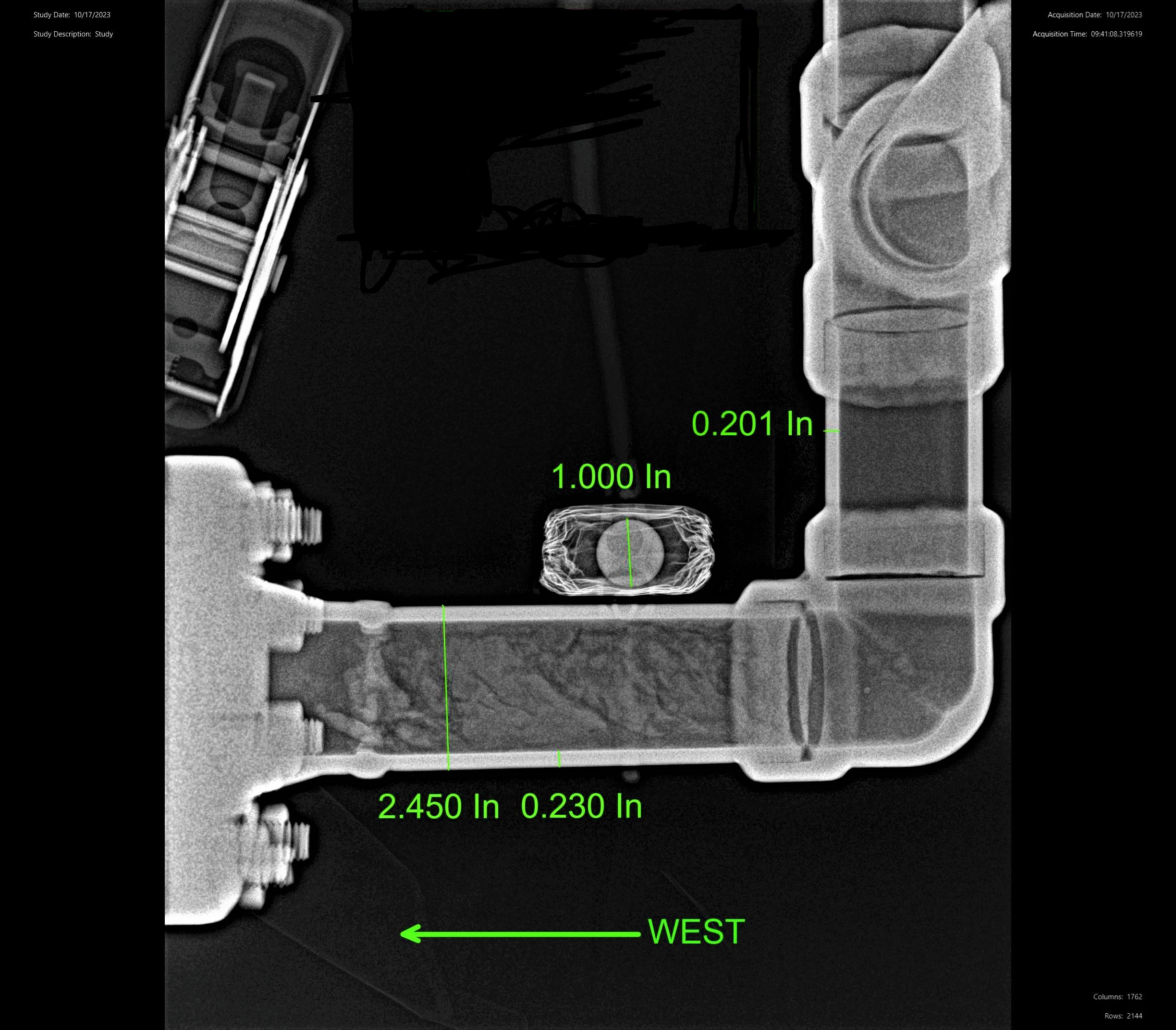
Digital radiography (DR) and computed radiography (CR) are advanced radiographic techniques that produce digital images, offering significant advantages over conventional film-based methods. Both techniques allow for post-processing to optimize image quality, and their wide dynamic range provides greater flexibility for various NDT and Inspection services applications. The elimination of chemicals and film, along with reduced exposure and faster image processing times, makes DR and CR a smart choice for many industries.
Key Advantages of DR:
- Very short exposure times reduce radiation exposure and save time
- Practically instant image processing allows for quick adjustments with minimal delays
Computed Radiography (CR):
CR replaces traditional film with photostimulable phosphor plates (PSPs) to capture images. The exposed PSPs are scanned, and the data is converted into a digital image file. Post-imaging processing software further enhances the image for evaluation.
Key Advantages of CR:
- Digital images can be securely stored on optical discs or other media, eliminating the need for physical film storage that degrades over time
- Viewing software includes measurement tools and other features to improve image evaluation
As part of NDT and Inspection services, digital radiography (DR) and computed radiography (CR) ensure compliance with ASME Code requirements while delivering efficient, high-quality imaging solutions for piping and vessel fabrication facilities.

ADVANCED NDT
Real-Time Radiography
Real-time radiography (RTR), utilizing a C-arm arrangement, is a highly effective tool for screening insulated piping for corrosion under insulation (CUI). This advanced NDT and Inspection service employs a low-energy X-ray source and a hand-held detector to deliver instant imagery of the surface profile of piping beneath insulation. When corrosion is detected, the data provided by RTR allows for targeted planning of further investigations and necessary repairs.
RTR for Corrosion Investigation:
RTR is an excellent screening tool for detecting CUI, offering significant advantages in terms of speed, efficiency, and cost savings. By providing focused information, RTR helps prevent unnecessary insulation removal, reducing downtime and expenses. Small, two-person RTR crews can quickly and efficiently access suspected CUI areas within facilities, giving clients ample time to plan prove-up inspections and equipment repairs.
Key Benefits of Real-Time Radiography (RTR):
- Instant imagery of piping surface profiles under insulation
- Substantial cost savings by avoiding unnecessary insulation removal
- Quick and efficient access to suspected CUI areas with minimal disruption
- Supports compliance with ASME Code requirements and enhances the integrity of piping and vessel fabrication facilities
As part of NDT and Inspection services, real-time radiography is a reliable and efficient solution for detecting and addressing corrosion under insulation (CUI), ensuring the safety and longevity of critical infrastructure.
ADVANCED NDT
Guided Wave Ultrasonics
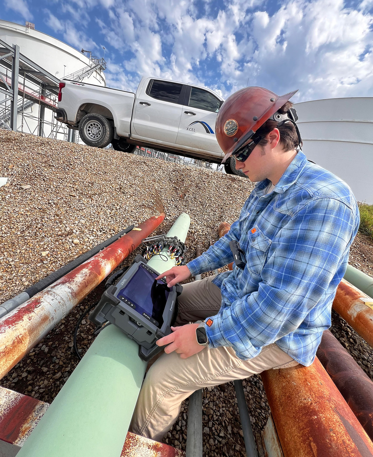
Guided wave ultrasonic testing (GWUT) is a highly effective NDT and Inspection service for screening corrosion in insulated, buried, or otherwise inaccessible piping. This advanced technique has become a preferred method for inspecting large piping segments due to its efficiency and ability to detect anomalies that can be further evaluated using quantitative NDT methods.
Key Benefits of Guided Wave Ultrasonic Testing (GWUT):
- Screens extensive piping segments for internal and external corrosion in just minutes from a single access point
- Detects anomalies in piping, enabling targeted follow-up inspections to assess severity
- Locates girth welds on insulated piping circuits for further inspection or maintenance
Primary Applications of GWUT:
- Insulated piping
- Buried piping
- Pipeline road crossings
Under optimal conditions, GWUT can screen many feet of piping quickly and efficiently, making it an invaluable tool for maintaining pipeline integrity. By providing reliable data on corrosion and other anomalies, guided wave ultrasonic testing supports compliance with ASME Code requirements and enhances the safety and reliability of piping and vessel fabrication facilities.
Technology based on Results.
- Automated Ultrasonic Corrosion Mapping
- Phased Array Ultrasonic Testing (PAUT)
- Time of Flight Diffraction (TOFD)
- Real Time Radiography (RTR)
- Guided Wave Ultrasonic Testing (GWUT)
- Digital Radiography (DR)
- Computed Radiography (CR)
- Eddy Current Testing (ECT)
Why choose XCEL?
- Multiple ASNT Level III technicians
- Qualified technicians with numerous Advanced NDT certifications
- Versatility and cross-utilization across service lines
- Advanced solutions for problems common to the oil and gas sector
- Our ASNT Level III instructors hold certifications in RT, PT, MT, VT, LT, UT, ET